Systems and methods for distributed interferometric acoustic monitoring

a distributed interferometer and acoustic monitoring technology, applied in the field of systems and methods for distributed interferometric acoustic monitoring, can solve the problems of insufficient inability to detect/analyse continuous data from wellbores, and insufficient production delay, so as to increase the acoustic sensitivity of fiber optics

Active Publication Date: 2009-05-07
SCHLUMBERGER TECH CORP
View PDF6 Cites 246 Cited by
  • Summary
  • Abstract
  • Description
  • Claims
  • Application Information

AI Technical Summary

Benefits of technology

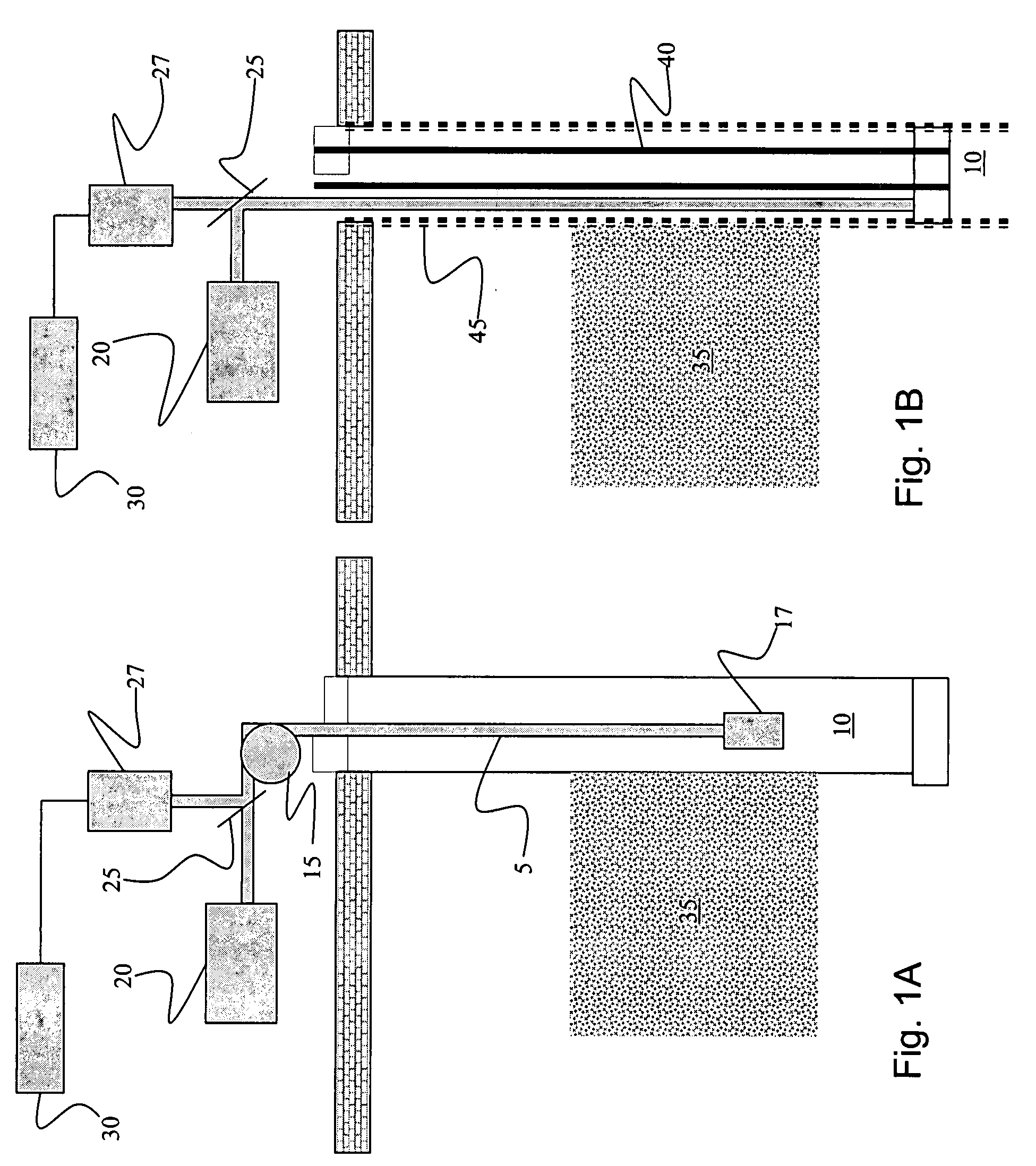
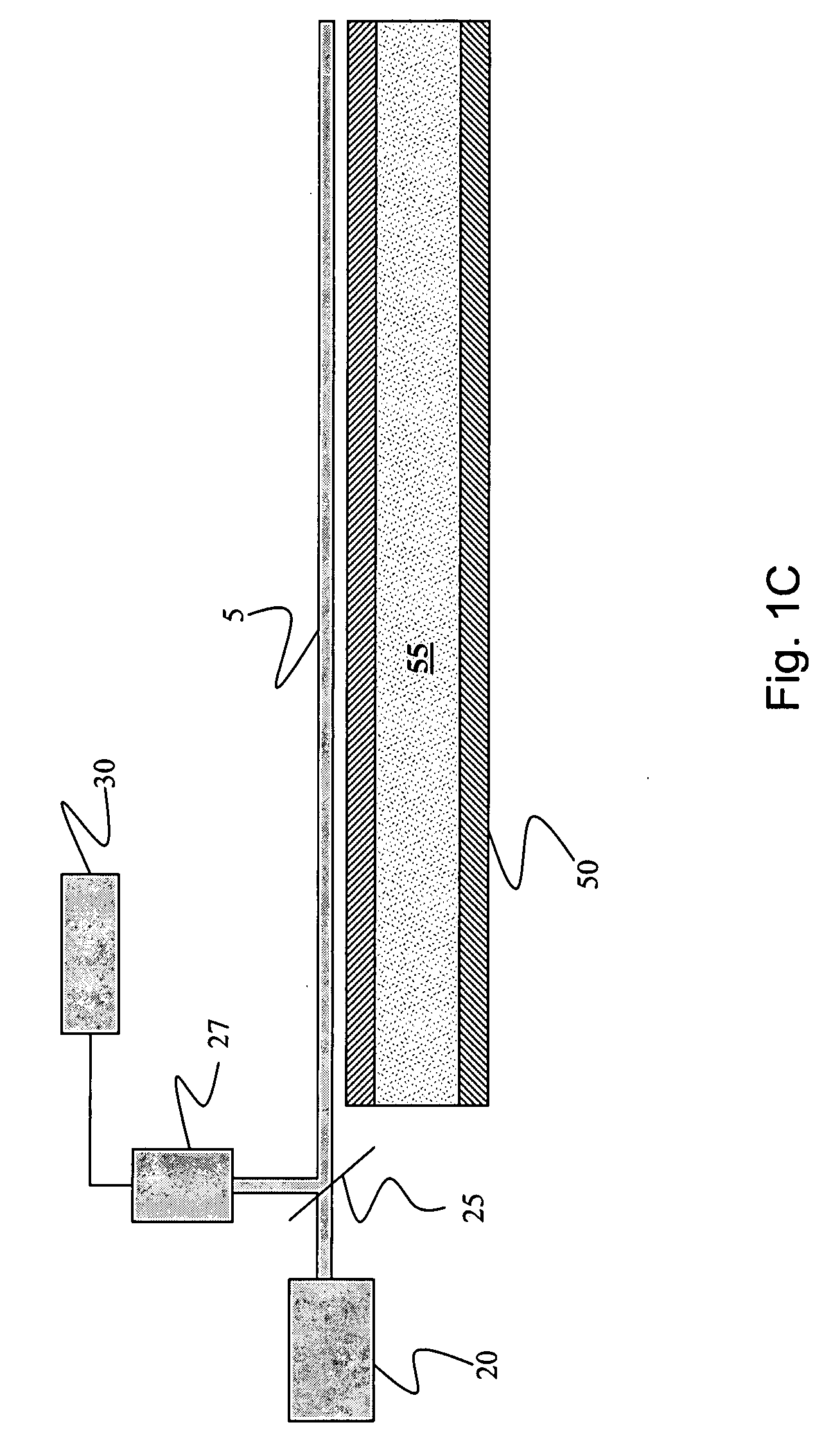
[0013]Some of the embodiments of the present invention provide for using the optical fiber to acoustically monitor the wellbore, conduit and / or reservoir. More specifically, but not by way of limitation, in one embodiment of the present invention, one or more optical fibers may be disposed along the wellbore or the conduit to act as a distributed acoustic sensor. In some embodiments, one or more acoustic transducers may be coupled along the fiber optic to increase the acoustic sensitivity of the fiber optic.

Problems solved by technology

Such use of wireline tools is invasive, may affect other operations being performed in the wellbore and / or operations it that might be desirable to perform in the wellbore when the wireline tool is deployed.
Use of wireline tools may be expensive, cause production delay and because the wireline tools may, in certain circumstances, have to be removed from the wellbore for other wellbore procedures to occur, may not provide for detecting / analyzing continuous data from the wellbore.
Similarly, with conduits containing hydrocarbons, periodic testing along / through the conduit as to the condition of the conduit, analysis of any material in and / or flowing in the conduit and / or analysis of the hydrocarbons in the conduit may also be invasive, expensive, cause production / transportation delay, only provide for sporadic monitoring, only provide for disjointed monitoring of specific locations along the conduit and / or the like.
These tools are not ideally suited to monitoring simultaneous events at multiple locations or for long period deployments.
In addition, it may be difficult to log below wellbore architecture like valves, packers or pumps.
Also the very fact of installing such a tool may change conditions such that the measured results are not representative of those when the tool is not present.
With regard to the wellbore, monitoring of sand in the wellbore may be of high important for certain types of wellbores, since the production of sand in the wellbore may have detrimental effects on production of hydrocarbons from the wellbore.
Sand may cause such detrimental effects as clogging well lines, adversely affecting pump operation, causing corrosion and / or erosion to pipes and associated equipment and / or the like.
Downhole monitoring of the treatment may show when gravel deposition along the screen is not progressing as desired, with either areas of low gravel concentration (possibly leading to voids) or very high concentrations (possibly leading to premature bridging).

Method used


Image

  • Systems and methods for distributed interferometric acoustic monitoring
  • Systems and methods for distributed interferometric acoustic monitoring
  • Systems and methods for distributed interferometric acoustic monitoring

Examples


Embodiment Construction

[0023]The ensuing description provides exemplary embodiments only, and is not intended to limit the scope, applicability or configuration of the disclosure. Rather, the ensuing description of the exemplary embodiments will provide those skilled in the art with an enabling description for implementing one or more exemplary embodiments. It being understood that various changes may be made in the function and arrangement of elements without departing from the spirit and scope of the invention as set forth in the appended claims.

[0024]Specific details are given in the following description to provide a thorough understanding of the embodiments. However, it will be understood by one of ordinary skill in the art that the embodiments may be practiced without these specific details. For example, systems, structures, and other components may be shown as components in block diagram form in order not to obscure the embodiments in unnecessary detail. In other instances, well-known processes, te...


PUM


Abstract

This disclosure relates in general to a method and system for monitoring a conduit, a wellbore or a reservoir associated with hydrocarbon production or transportation and / or carbon dioxide sequestration. More specifically, but not by way of limitation, embodiments of the present invention provide for using an optical fiber as a distributed interferometer that may be used to monitor the conduit, wellbore or reservoir. In certain aspects, the distributed interferometric monitoring provides

Description

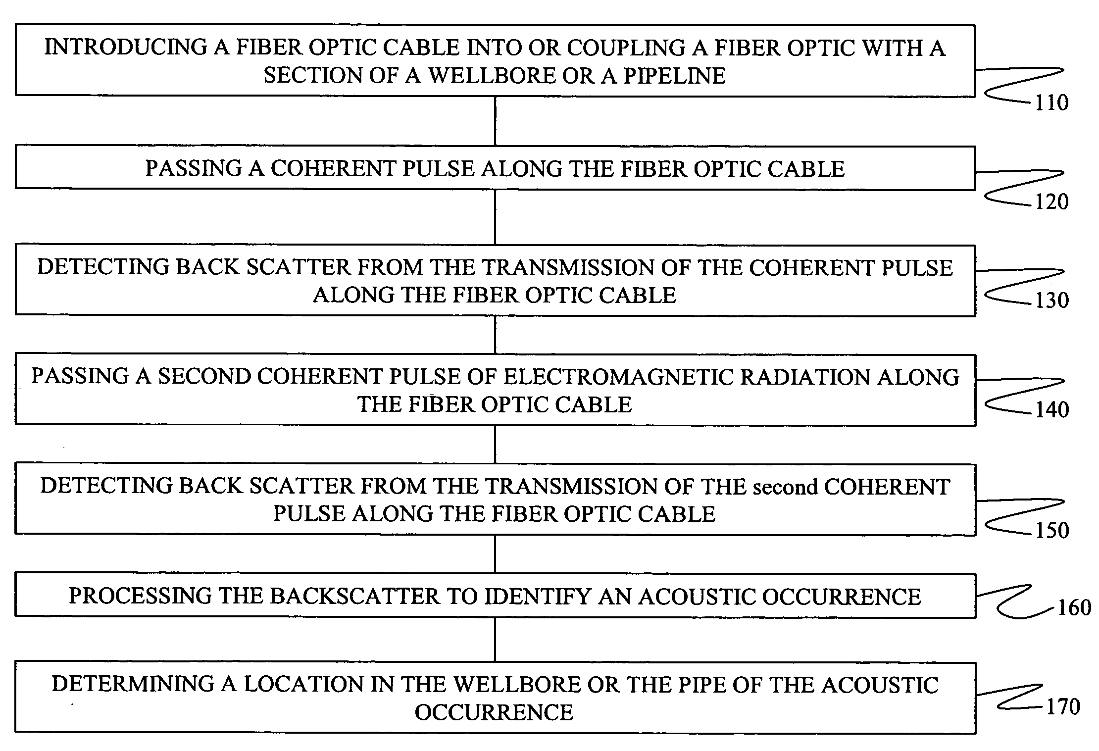
BACKGROUND OF THE INVENTION[0001]This disclosure relates in general to a method and system for monitoring a conduit, a wellbore or a reservoir associated with hydrocarbon production or transportation and / or carbon dioxide sequestration. More specifically, but not by way of limitation, embodiments of the present invention provide for using an optical fiber as a distributed interferometer that may be used to monitor the conduit, wellbore or reservoir.[0002]A wide variety of techniques have previously been used to monitor reservoirs, wellbores and / or pipes containing hydrocarbons, such as sub-sea pipelines, transportation pipelines and / or the like. Monitoring of wellbores may often occur during completion and / or production stages and monitoring may comprise monitoring reservoir conditions, estimating quantities of hydrocarbons (oil and gas), monitoring treatment of the wellbore—which may include monitoring treatment fluids applied to the wellbore, the effects of the treatment fluids an...

Claims


Application Information

Patent Timeline
Patent Type & Authority Applications(United States)
IPC IPC(8): E21B47/10
CPCE21B43/26G01V8/02G01V8/16Y02C10/14E21B47/06E21B47/123E21B41/0064G01V1/226E21B47/135Y02C20/40
Inventor HARTOG, ARTHUR H.BROWN, J. ERNESTCOOK, JOHN MERVYNELPHICK, JONATHANHAMMOND, PAUL S.JOHNSON, ASHLEY BERNARD
Owner SCHLUMBERGER TECH CORP
Why Eureka
Try Eureka