Discontinous tightening wrench comprising means for measuring dynamic events caused by this tightening on the casing of the wrench

a discontinuous clamping and wrench technology, applied in the field of industrial tools, can solve the problems of difficult monitoring of the effective torque applied in the screw, incorrect results, and frequent observation of incorrect results

Inactive Publication Date: 2009-05-07
ETAB GEORRENAULT
View PDF13 Cites 6 Cited by
  • Summary
  • Abstract
  • Description
  • Claims
  • Application Information

AI Technical Summary

Benefits of technology

[0038]In addition, the corresponding measurement means may be associated directly with the casing, which avoids having to fit sensors (angle or torque) on the rotating parts of the tool and remedies assembly and / or setting and / or maintenance difficulties caused by the sensors according to the prior art.
[0040]In this way, it is possible to optimise the processing of the vibrations measured, which makes it possible to improve the clamping level detection (or deduction) precision.
[0044]Such a component may be proposed in relatively small dimensions, enabling the easy integration thereof on the casing, without having a detrimental effect on the space requirements or handling of the tool.

Problems solved by technology

The major drawback is that it is difficult to monitor the effective torque applied in the screw.
Therefore, incorrect results, due to uncertain perception of the clamping level, are frequently observed.
The major drawback of these technologies is that they require the integration of sensors on the rotating parts, resulting in:assembly and / or setting difficulties;dependency with respect to wear parts liable to induce, in the long term, a reliability defect;complex maintenance operations.

Method used


Image

  • Discontinous tightening wrench comprising means for measuring dynamic events caused by this tightening on the casing of the wrench
  • Discontinous tightening wrench comprising means for measuring dynamic events caused by this tightening on the casing of the wrench
  • Discontinous tightening wrench comprising means for measuring dynamic events caused by this tightening on the casing of the wrench

Examples


first embodiment

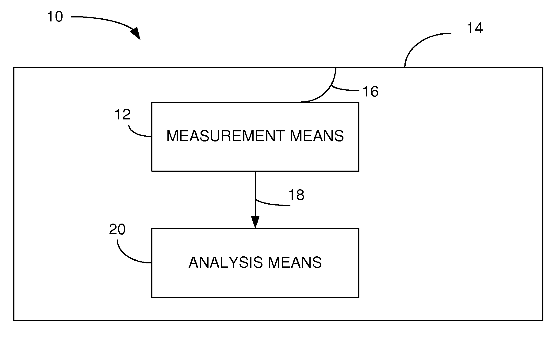
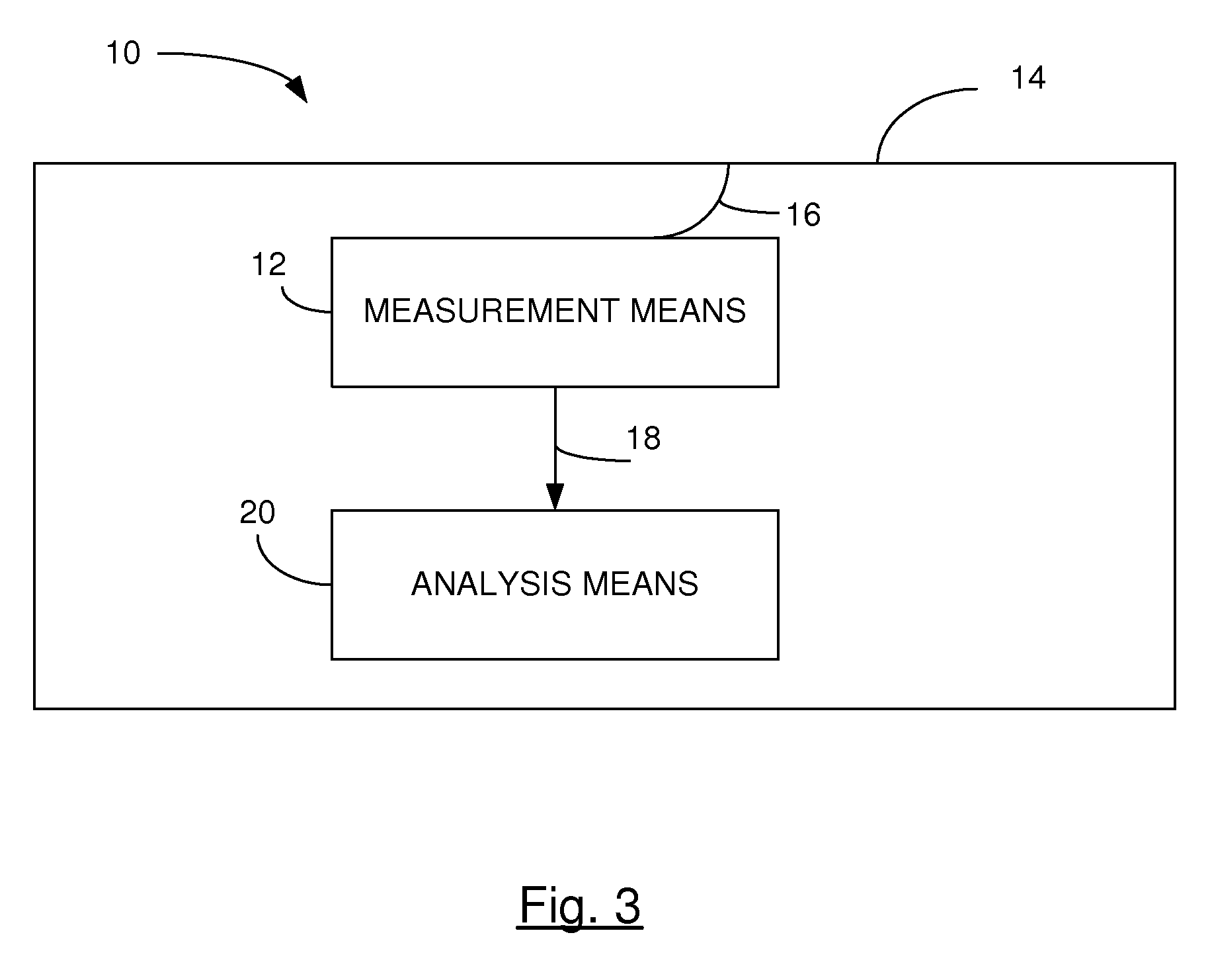
[0052]According to the invention, the tool includes one or more accelerometers 12 directly attached 16 on the casing 14 of the tool 10, with a view to detecting the vibrations of the casing.

[0053]This accelerometer measures the vibratory repercussions of the clamping process in the tool casing.

[0054]It is noted that an accelerometer is an acceleration sensor. A distinction is made between several categories of accelerometers:[0055]those able to measure a static acceleration (such as gravity);[0056]those able to measure a dynamic acceleration (vibrations);[0057]those able to measure either a static or dynamic acceleration.

[0058]Naturally, an embodiment of the invention provides for the use of an accelerometer to measure at least one dynamic acceleration.

[0059]The accelerometer used may be in the form of an electronic chip, produced using MEMS (Micro-Electro-Mechanical Systems) technology.

second embodiment

[0060]According to the invention, the tool includes one or more gyroscopes 12 attached on the casing so as to be able to detect and measure, with respect to an external reference, the rotation of the casing about the tool motor axis.

[0061]Frequential analysis means 20 of the signal 18 supplied by the accelerometer make it possible to determine whether the required clamping level has been reached.

[0062]An embodiment of the invention proposes a discontinuous clamping wrench that makes it possible to determine reliably whether a clamping level has been reached, using a simpler solution than those of the prior art.

[0063]An embodiment of the invention provides such a technique to determine the clamping level of a discontinuous clamping wrench, which simplifies the assembly and / or maintenance operations of the corresponding means.

[0064]An embodiment of the invention provides such a technique that is simple in design, and that is easy and inexpensive to implement.


PUM


Abstract

The invention relates to a discontinuous clamping wrench, of the type comprising a motor and a pulse clutch integrated in a casing, characterised in that it comprises measurement means of dynamic phenomena induced by said clamping on said casing, with a view to correlating said measurement with a clamping level.

Description

CROSS-REFERENCE TO RELATED APPLICATIONS[0001]This Application is a Section 371 National Stage Application of International Application No. PCT / EP2006 / 068531, filed Nov. 15, 2006 and published as WO 2007 / 057424A1 on May 24, 2007, not in English.STATEMENT REGARDING FEDERALLY SPONSORED RESEARCH OR DEVELOPMENT[0002]None.THE NAMES OF PARTIES TO A JOINT RESERCH AGREEMENT[0003]None.FIELD OF THE DISCLOSURE[0004]The field of the disclosure is that of industrial tooling. More specifically, the disclosure relates to discontinuous clamping wrenches, commonly referred to as impact wrenches or pulse wrenches.BACKGROUND OF THE DISCLOSURE[0005]Discontinuous clamping wrenches are tools widely used in the industrial sector, particularly in the field of motor vehicle manufacture.[0006]The principle of these wrenches consists of generating torque pulses, which are transmitted to the screw to be tightened.[0007]These pulses are themselves generated by a system comprising:[0008]a pneumatic motor;[0009]a ...

Claims


Application Information

Patent Timeline
Patent Type & Authority Applications(United States)
IPC IPC(8): B25B23/14
CPCB25B23/1405B25B21/02
Inventor PAPROCKI, NORBERT
Owner ETAB GEORRENAULT
Why Eureka
Try Eureka