System and method for minimizing mutual inductance coupling between coils in an electromagnetic tracking system

a technology of electromagnetic tracking system and mutual inductance coupling, which is applied in the field of electromagnetic tracking system, can solve the problems of electromagnetic tracking system limited electromagnetic tracking system, electromagnetic tracking system accuracy degradation, and electromagnetic tracking system electromagnetic field distortion

Inactive Publication Date: 2009-05-07
GENERAL ELECTRIC CO
View PDF15 Cites 76 Cited by
  • Summary
  • Abstract
  • Description
  • Claims
  • Application Information

AI Technical Summary

Problems solved by technology

However, electromagnetic tracking systems are known to suffer from accuracy degradation due to electromagnetic field distortion caused by the presence of an uncharacterized metal distorter within the tracking volume or electromagnetic fields of the electromagnetic tracking system.
The presence of an uncharacterized metal distorter within the tracking volume of the electromagnetic tracking system may create distortion of the electromagnetic fields of the electromagnetic tracking system.
This distortion may cause inaccuracies in tracking the position and orientation of medical devices and instruments by causing inaccuracies in position and orientation calculations of the coils of the elec

Method used


Image

  • System and method for minimizing mutual inductance coupling between coils in an electromagnetic tracking system
  • System and method for minimizing mutual inductance coupling between coils in an electromagnetic tracking system
  • System and method for minimizing mutual inductance coupling between coils in an electromagnetic tracking system

Examples


Embodiment Construction

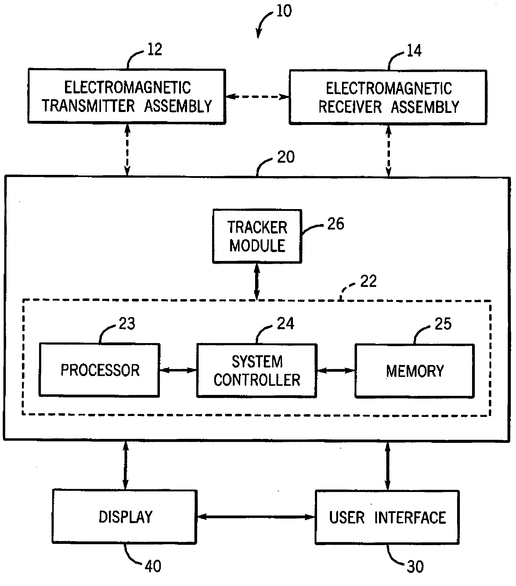
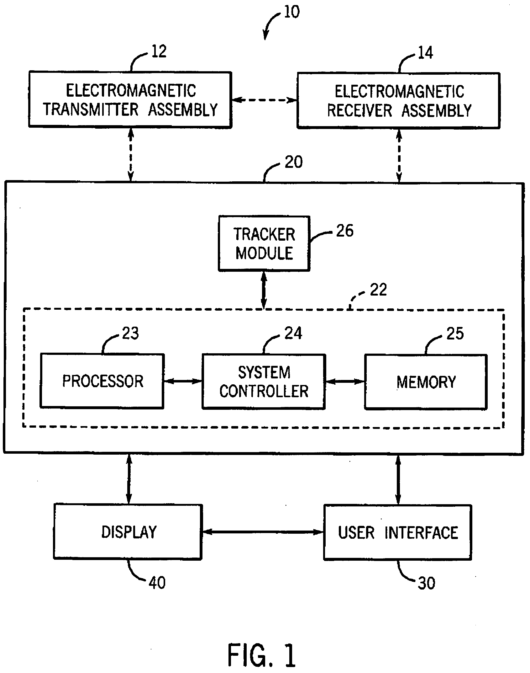
[0019]Referring now to the drawings, FIG. 1 is a block diagram illustrating an exemplary embodiment of an electromagnetic tracking system 10. The electromagnetic tracking system 10 comprises at least one electromagnetic transmitter assembly 12 with two or more coils and at least one electromagnetic receiver assembly 14 with two or more coils. The at least one electromagnetic transmitter assembly 12 with two or more coils is configured to minimize the mutual inductance coupling between the two or more coils.

[0020]The electromagnetic tracking system 10 further comprises a tracker workstation 20 coupled to and receiving data from the at least one electromagnetic transmitter assembly 12 and the at least one electromagnetic receiver assembly 14, a user interface 30 coupled to the tracker workstation 20, and a display 40 for visualizing imaging and tracking data. The tracker workstation 20 includes a tracking system computer 22 and a tracker module 26. The tracking system computer 22 incl...


PUM


Abstract

A system and method of minimizing the mutual inductance coupling between two or more coils of a coil array of an electromagnetic tracking system. The system involves a geometric arrangement of two or more coils, which significantly reduces any mutual inductance coupling between the two or more coils. The method involves characterization of two or more coils and compensating for mutual inductance coupling between the characterized two or more coils.

Description

BACKGROUND OF THE INVENTION[0001]This disclosure relates generally to an electromagnetic tracking system that uses electromagnetic fields to determine the position and orientation of an object, and more particularly to a system and method for minimizing the mutual inductance coupling between coils in an electromagnetic tracking system.[0002]Electromagnetic tracking systems have been used in various industries and applications to provide position and orientation information relating to objects. For example, electromagnetic tracking systems may be useful in aviation applications, motion sensing applications, retail applications, and medical applications. In medical applications, electromagnetic tracking systems have been used to provide an operator (e.g., a physician, surgeon, or other medical practitioner) with information to assist in the precise and rapid positioning of a medical device or instrument located in or near a patient's body during image-guided surgery. An electromagneti...

Claims


Application Information

Patent Timeline
IPC IPC(8): G01B7/14
CPCA61B2019/5251A61B19/5244A61B34/20A61B2034/2051
Inventor ANDERSON, PETER TRANEUSBEAUREGARD, GERALD LEE
Owner GENERAL ELECTRIC CO
Why Eureka
Try Eureka