Radio frequency animal tracking system

Inactive Publication Date: 2009-05-07
DESTRON FEARING CORP
View PDF25 Cites 44 Cited by
  • Summary
  • Abstract
  • Description
  • Claims
  • Application Information

AI Technical Summary

Benefits of technology

[0020]In an embodiment, the system can provide an animal identification tag. The animal identification tag can include an RFID system, a flexi

Problems solved by technology

Semi-active tags, which consume less power, tend to last longer.
However, even these tags must be replaced after a relatively short period of time.
Therefore, current RFID systems do not work well where fast data transmission is required, such as in certain real time tracking applications of fast moving objects.
More particularly, due to the inherent signal transmission delay associated with current RFID systems operated at 134.2 kHz, current systems cannot in certain circumstances effectively query and retrieve identification numbers, also commonly referred to as identification codes, from identification tags as the animals move rapidly past a particular point in space, such as when cattle move along a cattle chute commonly found at auctions or disassembly plants.
Unique challenges are associated with tracking livestock.
This complex mu

Method used


Image

  • Radio frequency animal tracking system
  • Radio frequency animal tracking system
  • Radio frequency animal tracking system

Examples


first embodiment

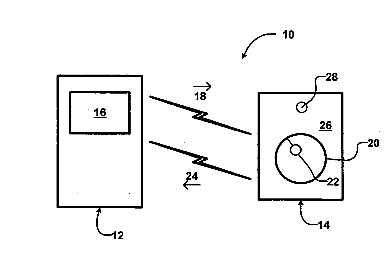
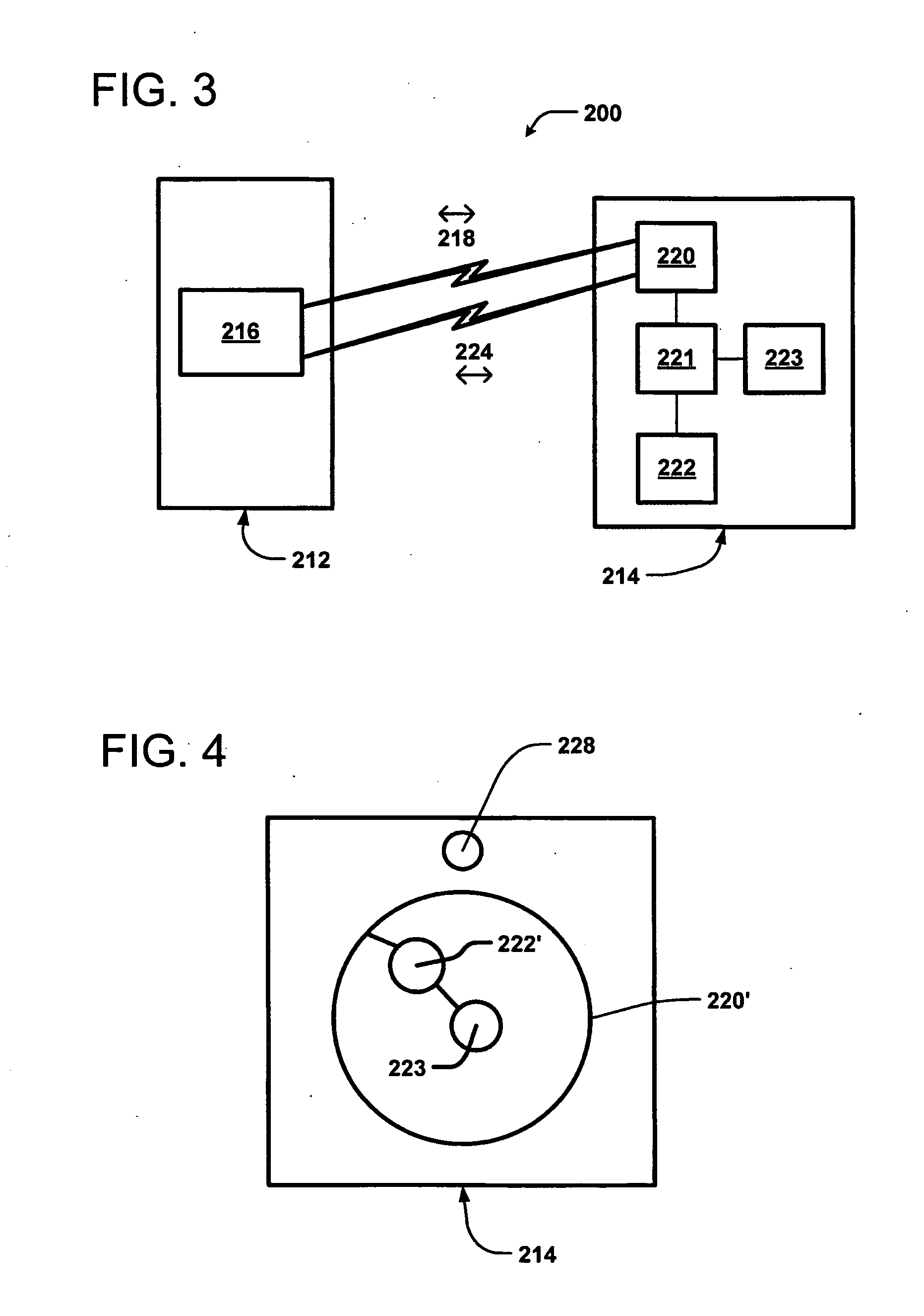
[0070]Referring now to FIGS. 3-6, there are a variety of combinations of fully- and semi-powered transmission capabilities that may be included within the present invention. a tag management system 200 includes a base station 212, also commonly referred to as a reader, and a transponder 214, also commonly referred to as an identification tag.

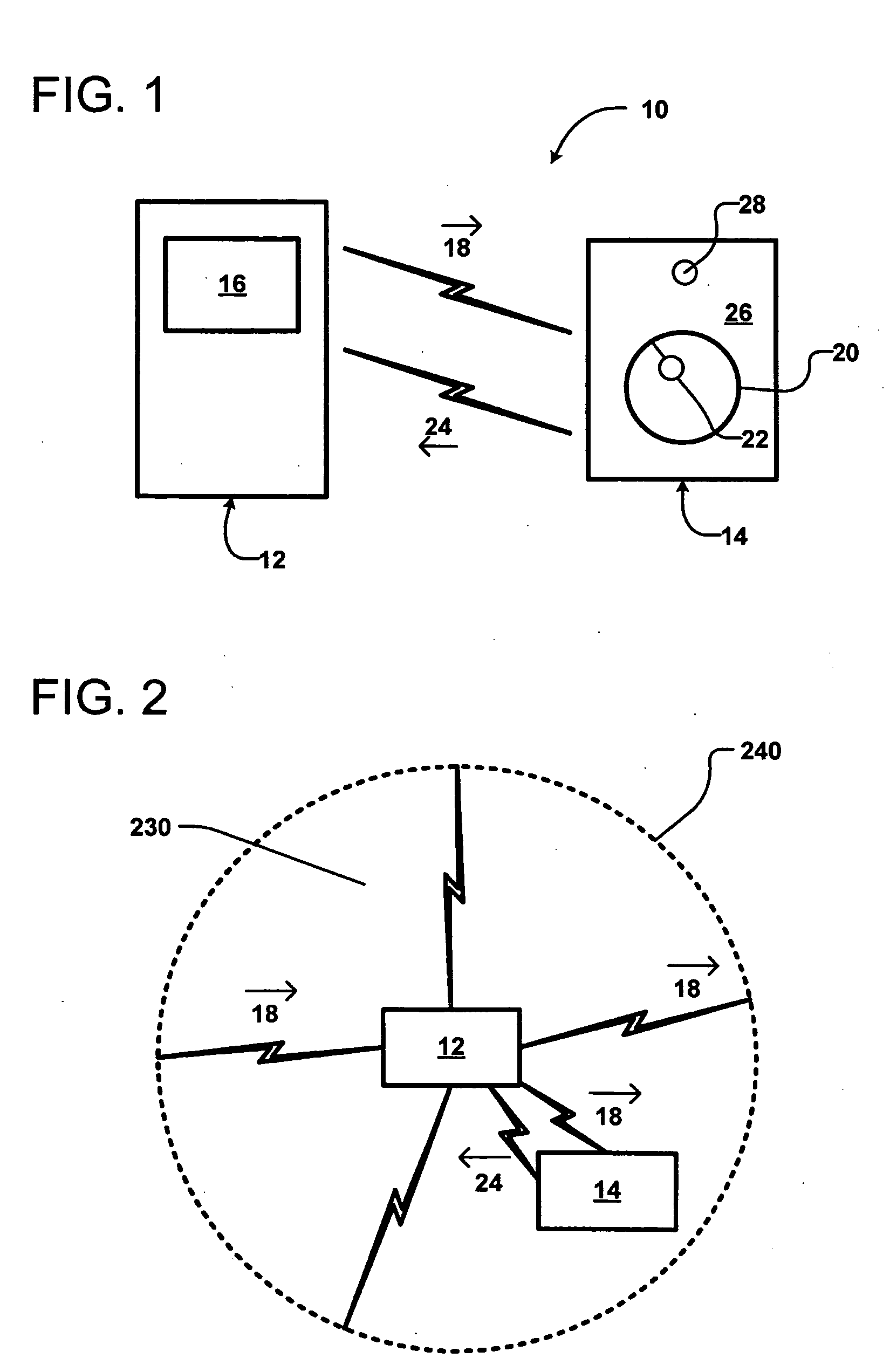
[0071]The base station 212 includes a transceiver 216 for emitting and receiving radio waves 218 to generate an electromagnetic field 230 over a geographic area 240 (see FIG. 5). In one embodiment, the frequency of the radio waves can be the standard frequency of 134.2 kHz. Of course, higher and lower radio wave frequencies are consistent with the scope of the disclosure. In some embodiments, the electromagnetic field 230 produced by the base station 212 is maintained over the geographic area 240 continuously. In other embodiments, the field 230 is generated at predetermined intervals. In one embodiment, the field 230 is generated at regular, pe...

embodiment 130

[0122]As shown in FIG. 15, a string of tags 122 formed on substrate 100 is maintained in a continuous strip 124, which may be fanfolded, rolled or otherwise packaged for sending to a producer, an auction lot, or other location within the animal production process. In an embodiment, tags 122 in strip 124 are inserted within a printing and encoding device 130 that may be positioned chute or corral side for ease of operation. Each of the tags 122 is pre-molded and encoded with a government issued identifier. Each of the tags 122 also includes area 128 for printing, embossing or otherwise marking with a local or management identifier. Area 128 allows a printing head 134 of chute side printer and encoder 130 to be used to apply a specific marking immediately prior to tag 122 being attached to the animal. While a novel printer / encoder embodiment 130 is described and shown herein, it is anticipated that tags 122 and strip 124 may be used with conventional printers currently in use for prin...


PUM


Abstract

An RFID system provides a transponder having a power store that can be recharged when located within an electromagnetic field generated by a transceiver unit. The power store can be a battery and/or a capacitor. In certain embodiments, the transponder can communicate over at least two different frequencies so that the real time performance of the transponder can be improved without losing backwards compatibility. The system provides an ear tag for use on livestock with superior durability and overall performance in the field.

Description

FIELD OF THE INVENTION[0001]The invention relates to a radio frequency identification system and more particularly to a radio frequency identification system for tracking animals.BACKGROUND OF THE INVENTION[0002]Radio frequency identification (RFID) systems are well known. RFID systems are active systems, wherein the transponder includes its own power source, semi-active, wherein a battery is used to power the memory storage, but not the transceiver, or passive systems, wherein the transponder receives all of its power from a base station. Since passive RFID systems do not require their own power source they are generally smaller, lighter, and cheaper to manufacture than active RFID systems. Consequently, passive systems are more commonly employed in RFID systems for the purpose of tracking as compared to active systems.[0003]Passive RFID systems are generally either inductively coupled RFID systems or capacitively coupled RFID systems. Passive inductively coupled RFID systems are p...

Claims


Application Information

Patent Timeline
IPC IPC(8): H04Q5/22
CPCH04Q9/00H04Q2209/47H04Q2209/756H04Q2209/883H04Q2209/886A01K11/006A01K29/005
Inventor GEISSLER, RANDOLPH K.LEWIS, STEVENNELSON, SCOTT ALAN
Owner DESTRON FEARING CORP
Why Eureka
Try Eureka