Position sensor and bias magnetic field generating device

Active Publication Date: 2009-05-07
DMG MORI SEIKI CO LTD
View PDF2 Cites 12 Cited by
  • Summary
  • Abstract
  • Description
  • Claims
  • Application Information

AI Technical Summary

Benefits of technology

[0013]In accordance with an embodiment of the present invention, there is provided a position sensor including: a magnetic recording medium including two incremental layers and an absolute layer, the absolute layer provided between the incremental layers, each of said layers having magnetic information recorded therein; and a magnetic detection section including three magnetoresistance effect devices opposite to the layers of the magnetic recording medium, being moved relative to the magnetic recording medium in the extending direction of the layers, and being operative to detect the magnetic information in the layers by the magnetoresistance effect devices, wherein the magnetic detection section has a bias magnetic field generating section disposed opposite to the magnetoresistance effect devices and operative to generate bias magnetic fields corresponding to the magnetoresistance effect devices.
[0014]In accordance with another embodiment of the present invention, there is provided a bias magnetic field generating device to be applied to a position sensor, the position sensor including: a magnetic recording medium including two incremental layers and an absolute layer, the absolute layer provided bet

Problems solved by technology

Therefore, if the bias magnetic field is designed according to the incremental layer, the sensitivity of the MR sensor in relation to the absolute layer would be lowered and the accuracy in detecting the magnetic infor

Method used


Image

  • Position sensor and bias magnetic field generating device
  • Position sensor and bias magnetic field generating device
  • Position sensor and bias magnetic field generating device

Examples


Example

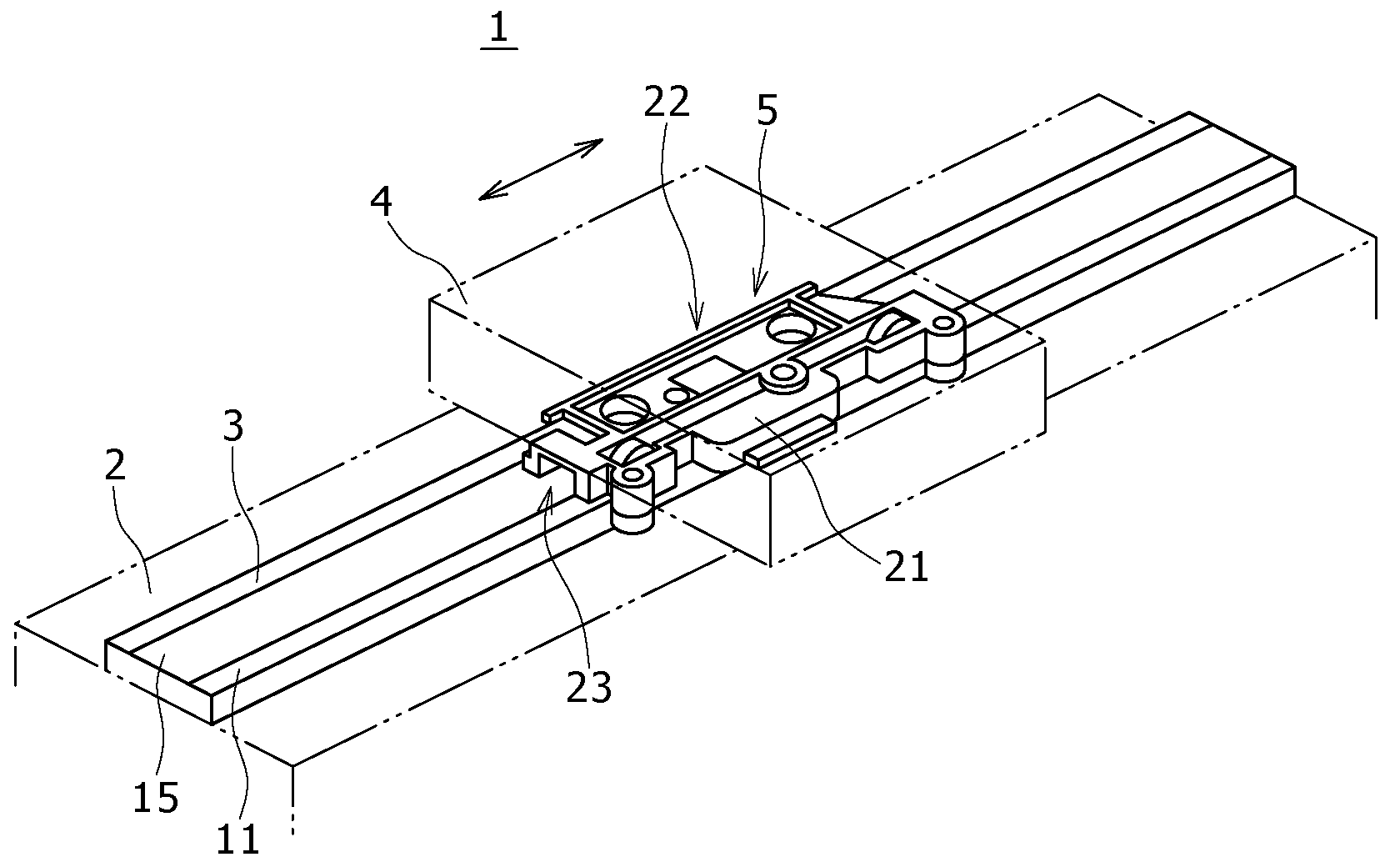
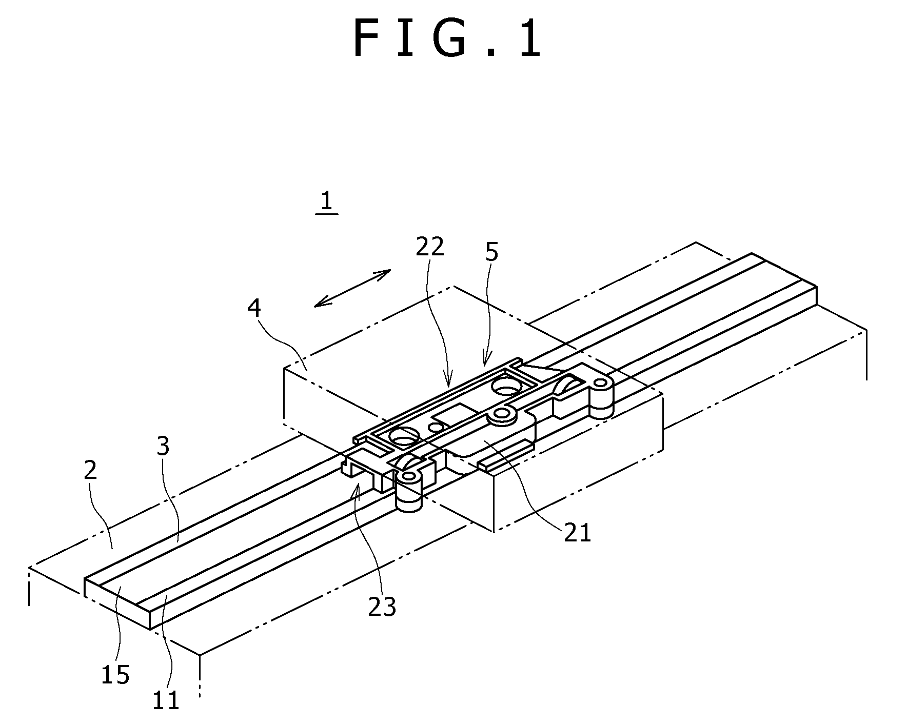
[0023]Some specific embodiments of the present invention will be described in detail below, referring to the drawings. As shown in FIG. 1, a position sensor 1 according to an embodiment of the present invention, which is provided for a machine tool, an industrial machine, a precision length / angle measuring instrument or the like, includes a scale member 3 mounted to a mount base part 2 provided on the side of a work carrier, for example, of a machine tool, and a sensor unit 5 which is provided on the side of a tool slide 4, disposed opposite to the scale member 3 and operative as magnetic detection means.

[0024]When the tool slide 4 is moved relative to the work carrier, the position sensor 1 momentarily detects the relative position, i.e., the position of machining of the work by a cutter mounted to the tool slide 4, and outputs a detection signal to a control unit of the machine tool.

[0025]Incidentally, the position sensor 1 is not limited to the above-mentioned structure. For exam...


PUM


Abstract

Disclosed herein is a position sensor including, a magnetic recording medium including two incremental layers and an absolute layer, the absolute layer provided between the incremental layers, each of the layers having magnetic information recorded therein, and a magnetic detection section including three magnetoresistance effect devices opposite to the layers of the magnetic recording medium, being moved relative to the magnetic recording medium in the extending direction of the layers, and being operative to detect the magnetic information in the layers by the magnetoresistance effect devices.

Description

CROSS REFERENCES TO RELATED APPLICATIONS[0001]The present invention contains subject matter related to Japanese Patent Application JP 2007-274092 filed in the Japan Patent Office on Oct. 22, 2007, the entire contents of which being incorporated herein by reference.BACKGROUND OF THE INVENTION[0002]1. Field of the Invention[0003]The present invention relates to a position sensor such as magnetic scales and rotary encoders, to be applied to machine tools, industrial machines, precision length / angle measuring instruments, etc. and a bias magnetic field generating device to be used in the position sensor.[0004]2. Description of the Related Art[0005]Hitherto, as a detection head of a position sensor such as magnetic scales and rotary encoders to be applied to machine tools, industrial machines, precision length / angle measuring instruments, etc., a magnetoresistance effect device (MR device) which utilizes the magnetoresistance effect of a thin film of Fe—Ni, Ni—Co or the like has been use...

Claims


Application Information

Patent Timeline
IPC IPC(8): G11B5/33
CPCG01D5/145G01D5/2455G01D5/24438
Inventor NAKAGAWA, NOBUHIRONAKAMURA, GUNICHIKUSUMI, MASAAKI
Owner DMG MORI SEIKI CO LTD
Why Eureka
Try Eureka