Method of programming cell in memory and memory apparatus utilizing the method

a programming cell and memory technology, applied in the field of memory device operation, can solve the problems of reduced programming efficiency, easy punch-through issue of unselected cells coupled to bit lines coupled to programmed cells, and reduced programming efficiency, so as to improve the efficiency of hot carrier injection and accelerate more efficiently

Active Publication Date: 2009-05-07
MACRONIX INT CO LTD
View PDF9 Cites 5 Cited by
  • Summary
  • Abstract
  • Description
  • Claims
  • Application Information

AI Technical Summary

Benefits of technology

[0024]Since the voltage difference for programming is applied between an S / D region of a selected cell and the S / D region of a neighboring cell not shared with the selected cell, punch-through of unselected cells is inhibited. Moreover, as the voltage applied to the shared second S / D region is higher, by a suitable range, than a voltage at which the electron current from the third S / D region to the second one is larger than that from the second S / D region to the first one, the carriers in the channels of the two cells can be accelerated more efficiently to improve the hot carrier injection efficiency.

Problems solved by technology

The cell needs a smaller area, but the unselected cells coupled to the bit lines coupled to the programmed cell easily suffer from a punch-through issue.
Though a certain raise in Vs prevents punch-through of unselected cells in the programming, the programming efficiency is reduced thereby.
Each cell needs a small area and punch-through of unselected cells is avoided due to the reduced electric field in this case, but the programming efficiency is reduced due to more electron scattering.

Method used


Image

  • Method of programming cell in memory and memory apparatus utilizing the method
  • Method of programming cell in memory and memory apparatus utilizing the method
  • Method of programming cell in memory and memory apparatus utilizing the method

Examples


first embodiment

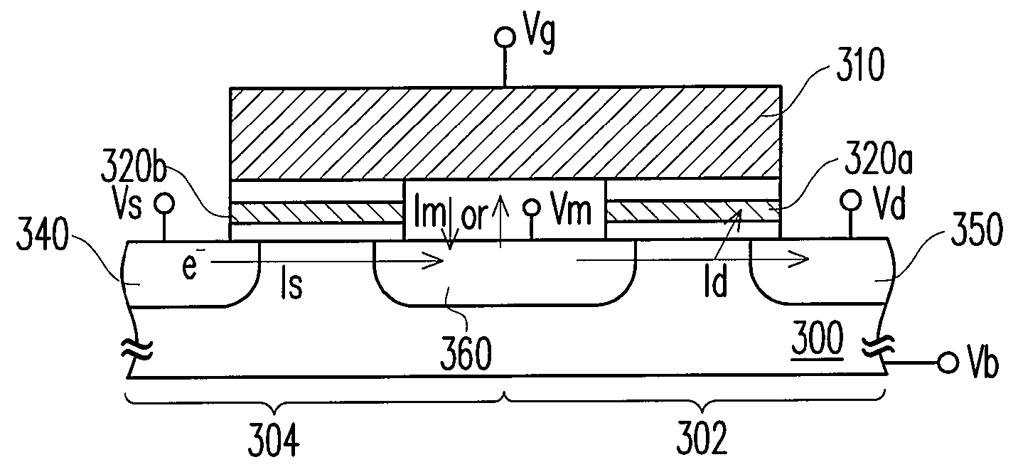
[0033]FIG. 4 illustrates a method of programming a cell in a non-volatile memory according to this invention.

[0034]Referring to FIG. 4, in the non-volatile memory, a cell 302 has a charge storage layer 320a and an N-type S / D region 350 in the substrate 300 and shares an N-type S / D region 360 with a neighboring cell 304, which has a charge storage layer 320b and an N-type S / D region 340 opposite to the S / D region 360. The control gates 310 of the cells 302 and 304 are contiguous and may be two portions of a word line. The storage layers 320a and 320b may be floating gates or charge trapping layers. As the storage layers 320a and 320b are floating gates, they can be separated from the control gates 310 by an ONO composite layer. When the charge storage layers 320a and 320b are charge trapping layers, they may include silicon nitride (SiN).

[0035]In this embodiment, the programming of the cell 302 is exemplified. A voltage Vb (0V or a negative voltage like −1V) is applied to the substra...

second embodiment

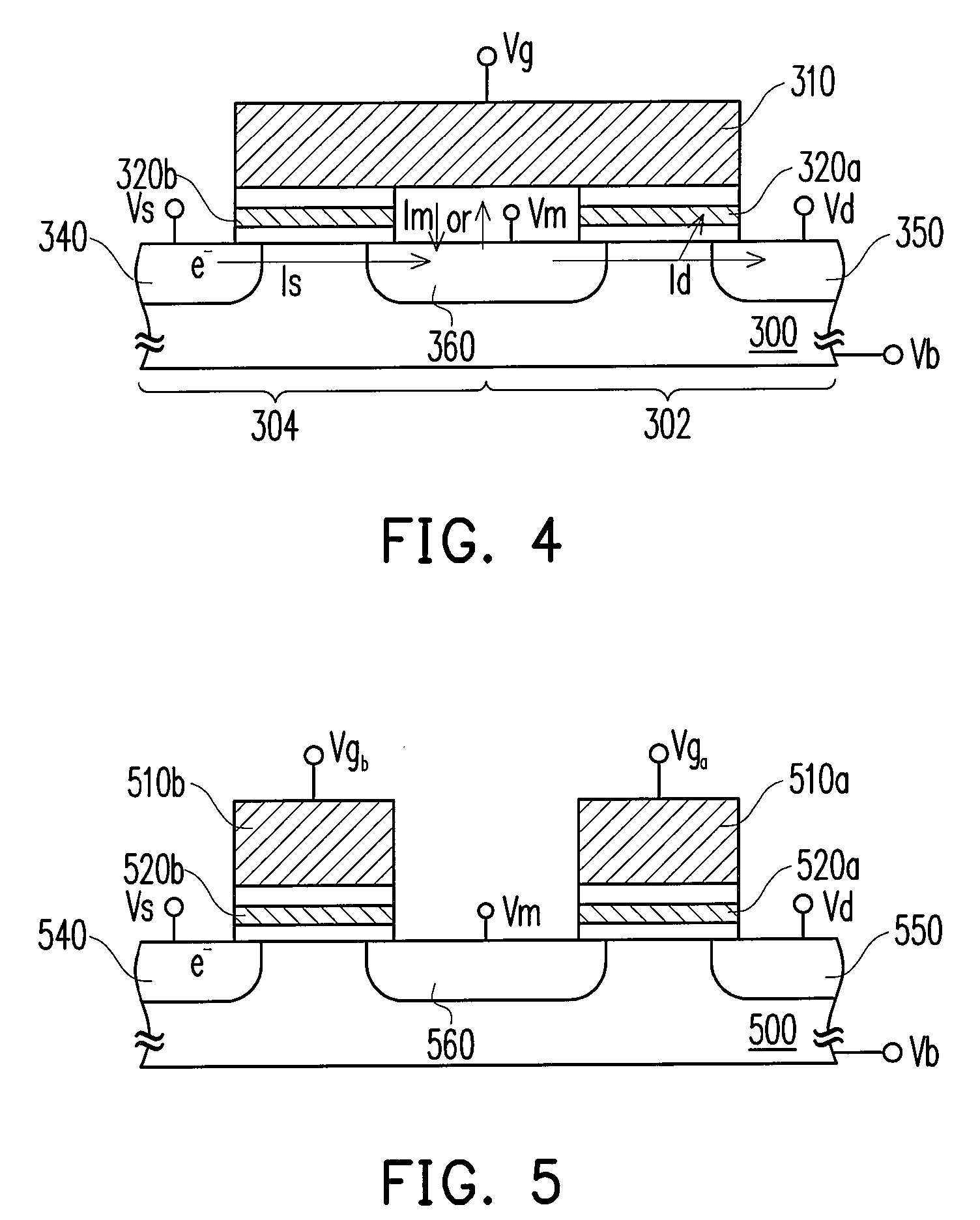
[0036]FIG. 5 illustrates a method of programming a cell in a non-volatile memory according to this invention.

[0037]Referring to FIG. 5, in the non-volatile memory, a first cell has a charge storage layer 520a and an N-type S / D region 550 in the substrate 500 and shares an N-type S / D region 560 with a neighboring second cell that has a storage layer 520b and an N-type S / D region 540 opposite to the S / D region 560. The two control gates 510a and 510b of the first and the second cell are separated from each other, wherein each of the two control gates 510a and 510b may be a portion of a word line. The storage layers 520a and 520b may be floating gates or charge trapping layers as in the first embodiment.

[0038]In this embodiment, the programming of the first cell is taken as an example. The programming process is similar to that described in the first embodiment except that two positive gate voltages Vga and Vgb are respectively applied to the control gates 510a and 510b to turn on the ...


PUM


Abstract

A method of programming a first cell in a memory, wherein the first cell has a first S/D region and shares a second S/D region with a second cell that has a third S/D region opposite to the second S/D region. The channels of the first and the second cells are turned on, a first voltage is applied to the first S/D region, a second voltage is applied to the second S/D region and a third voltage is applied to the third S/D region. The second voltage is between the first voltage and the third voltage, and the first to third voltages make carriers flow from the third S/D region to the first S/ID region and cause hot carriers in the channel of the first cell to be injected into the charge storage layer of the first cell.

Description

CROSS-REFERENCE TO RELATED APPLICATION[0001]This application claims the priority benefit of U.S.A. provisional application Ser. No. 60 / 985,966, filed on Nov. 6, 2007. The entirety of the above-mentioned patent application is hereby incorporated by reference herein and made a part of this specification.BACKGROUND OF THE INVENTION[0002]1. Field of Invention[0003]This invention relates to operation of memory devices, and more particularly to a method of programming a cell in a memory (array) that shares an S / D region with another cell, and to a memory apparatus utilizing the method.[0004]2. Description of Related Art[0005]Non-volatile memory devices have been widely used in the fields of long-term storage as being able to retain data without a power and having smaller sizes. For the convenience of use, most of current non-volatile memory devices are programmed and erased electrically. FIGS. 1-3 respectively illustrate three types of non-volatile memory cell and their respective program...

Claims


Application Information

Patent Timeline
Patent Type & Authority Applications(United States)
IPC IPC(8): G11C11/34
CPCG11C16/10
Inventor TSAI, WEN-JERWANG, TA-HUILEE, CHIH-WEI
Owner MACRONIX INT CO LTD
Why Eureka
Try Eureka