
Method and apparatus for testing and evaluating machine components under simulated in-situ thermal operating conditions

a technology for evaluating machine components and operating conditions, applied in the direction of vibration measurement in solids, instruments, using mechanical means, etc., can solve the problems of repeated thermal stresses to which the component may be subjected, no simple, inexpensive and accurate method or apparatus available for testing and evaluating individual parts or components of turbine engines, and take a long time to perform. , to achieve the effect of simple, inexpensive and accura

Inactive Publication Date: 2009-05-07
GENERAL ELECTRIC CO
View PDF6 Cites 18 Cited by
  • Summary
  • Abstract
  • Description
  • Claims
  • Application Information

AI Technical Summary

Benefits of technology

[0007]Another aspect of the non-limiting exemplary implementation described herein is the provision of a gas turbine engine part / component testing apparatus and method capable of simulating in-situ thermal operating conditions of the component for evaluating and validating new component geometries, designs as well as component repair techniques without necessitating the labor and expense of conducting a full turbine engine test to test a single component.
[0009]A further aspect of the non-limiting exemplary implementation disclosed herein is the provision of a method and apparatus for testing and evaluating machine components of various geometries under in-situ thermal conditions in a relatively expeditious and inexpensive manner.
[0012]Yet still another aspect of the non-limiting example test apparatus and method implementation described herein is an ability to replicate the in-service conditions and environment of a variety of machine components so as to enable providing a simple, inexpensive and accurate method for evaluation of the effectiveness of new component designs or component repair technique.
[0013]Yet still another aspect of the non-limiting example test apparatus and method implementation described herein is the potential for implementing a crack initiation and propagation test method which, through the use of forced heating and / or forced cooling cycles, can effectively simulate engine operation cycles and perform aggressive testing in an accelerated fashion over a shorter period of time.

Problems solved by technology

As with many industrial and commercial machine components, and in particular with gas turbine engine components, one preeminent factor in the formation of cracks within a component is the repetitive thermal stresses to which the component may be subjected during use.
In the past, there was no simple, inexpensive and accurate method or apparatus available for testing and evaluating individual parts or components of turbine engines under actual thermal operating conditions to obtain accurate and reliable crack initiation and propagation data.
Conventionally, methods for predicting the potential success of a new part / component design or component repair procedure / technique typically entail evaluating a particular component in-situ under actual operating conditions either by performing a comprehensive full operational test of a particular individual turbine engine or by performing a so called “fleet leader” test either of which can take a very long time to perform and both of which are fairly expensive to implement.

Method used


Image

  • Method and apparatus for testing and evaluating machine components under simulated in-situ thermal operating conditions
  • Method and apparatus for testing and evaluating machine components under simulated in-situ thermal operating conditions
  • Method and apparatus for testing and evaluating machine components under simulated in-situ thermal operating conditions

Examples


Embodiment Construction

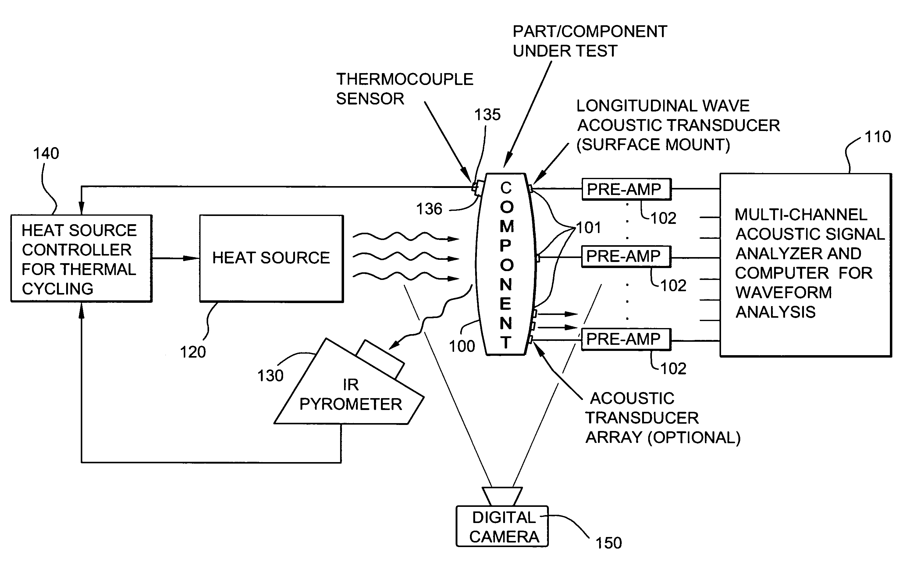
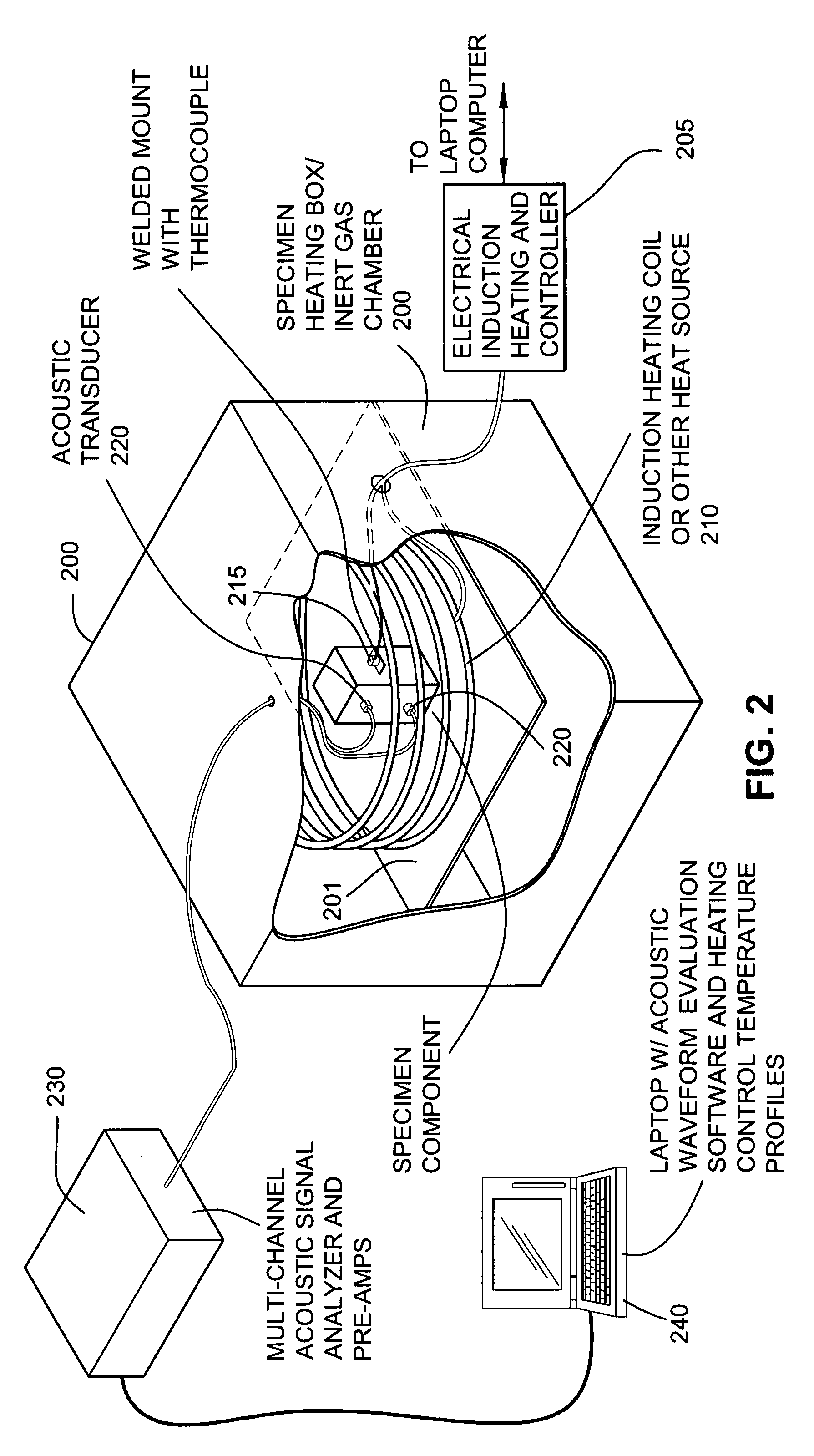
[0016]FIG. 1 is a basic functional block diagram for a exemplary implementation of a system that combines cyclic heating and / or cooling with acoustic emission monitoring for the purpose of testing and evaluating an individual machine component (i.e., a specimen component) under simulated in-situ thermal operating conditions. In the non-limiting example implementation disclosed herein, the energy and amplitude of spontaneously occurring acoustic “hits” (i.e., sonic or vibrational emissions greater than a predetermined threshold or amplitude) detected during a repeated cycle of heating a machine component, then allowing it to cool off, are recorded and analyzed for the purpose of obtaining data on the initiation and propagation of cracks in the component's structure, among other things. The number of heating-cooling cycles required to initiate a crack and / or the number of heating-cooling cycles needed to propagate a crack to a predetermined size / distance within the tested component ar...


PUM


Abstract

A method and apparatus is described for enabling the testing and evaluation of industrial machine components and, in particular, gas turbine engine components, under simulated in-situ thermal operating conditions for effectively evaluating new component designs and repair techniques. A specimen machine component / part is placed in a test chamber and cyclically heated and cooled while being monitored to obtain information regarding the initiation and propagation of a crack within the structure of the component. Information regarding the number of heating and cooling cycles sustained by the component until crack initiation and information indicating the rate of crack propagation are acquired and compared over multiple heating-cooling cycles to evaluate components and repair techniques. In one example implementation, the component is monitored during cyclic heating-cooling for spontaneous acoustic emissions and acoustic emission waveform data is recorded and analyzed to determine crack initiation and / or propagation.

Description

BACKGROUND OF THE INVENTION[0001]The subject matter disclosed herein relates generally to a method and apparatus for testing and evaluating new or repaired machine components to obtain data on crack initiation and propagation, and more particularly, to a method and apparatus for testing and evaluating new and repaired turbine engine components subjected to cyclical thermal stresses to obtain data on crack initiation and propagation.[0002]In the field of gas turbine engine design and repair engineering, it is highly desirable to be able to accurately evaluate new mechanical / structural designs of turbine engine components as well as reliably validate new or different component repair techniques before implementing such in the field. It is also known that effective evaluation of the structural integrity and durability of a new component design or of a repaired machine component is based at least in part upon obtaining accurate information on the initiation and propagation of cracks tha...

Claims


Application Information

Patent Timeline
IPC IPC(8): G01N25/72G01N29/14G01N19/08G01M99/00
CPCG01N29/14G01N25/72
Inventor O'CONNELL, MATTHEW J.THOMPSON, CHRISTOPHER E.DIMASCIO, PAUL S.
Owner GENERAL ELECTRIC CO
Learn More