
Subscriber calling method (variants) and a communications device system for carrying out said method

a communication device and subscriber technology, applied in the field of subscriber calling, can solve the problems of unfavorable subscriber calling and appear to be rather dangerous to subscriber

Inactive Publication Date: 2009-05-07
MOLODCHENKO NIKOLAY ALEKSEEVICH +1
View PDF1 Cites 2 Cited by
  • Summary
  • Abstract
  • Description
  • Claims
  • Application Information

AI Technical Summary

Benefits of technology

"The invention is a multi-purpose telephone unit that can access any communication system without limitation and with a free choice of user identification. The unit can make and receive calls, access data transmission systems, and work with different types of telephone networks. The invention solves the problem of being unable to make calls when the exact location of the communication device with a definite identifier is unknown. The invention also allows for the use of both personal subscriber calling methods, providing more flexibility and security."

Problems solved by technology

Disadvantages of subscriber calling method and communication devices system which are currently in use consist in impossibility of making subscriber call when exact location of communication terminal device with definite identifier is unknown.
Radio transmitter of subscriber's terminal device must work in radiation mode with high periodicity both during communication session and all other time (for positioning), this appears to be rather dangerous to subscriber.

Method used


Image

  • Subscriber calling method (variants) and a communications device system for carrying out said method
  • Subscriber calling method (variants) and a communications device system for carrying out said method
  • Subscriber calling method (variants) and a communications device system for carrying out said method

Examples


Embodiment Construction

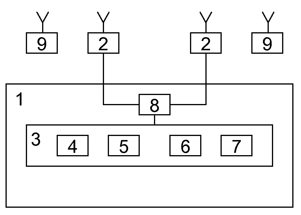
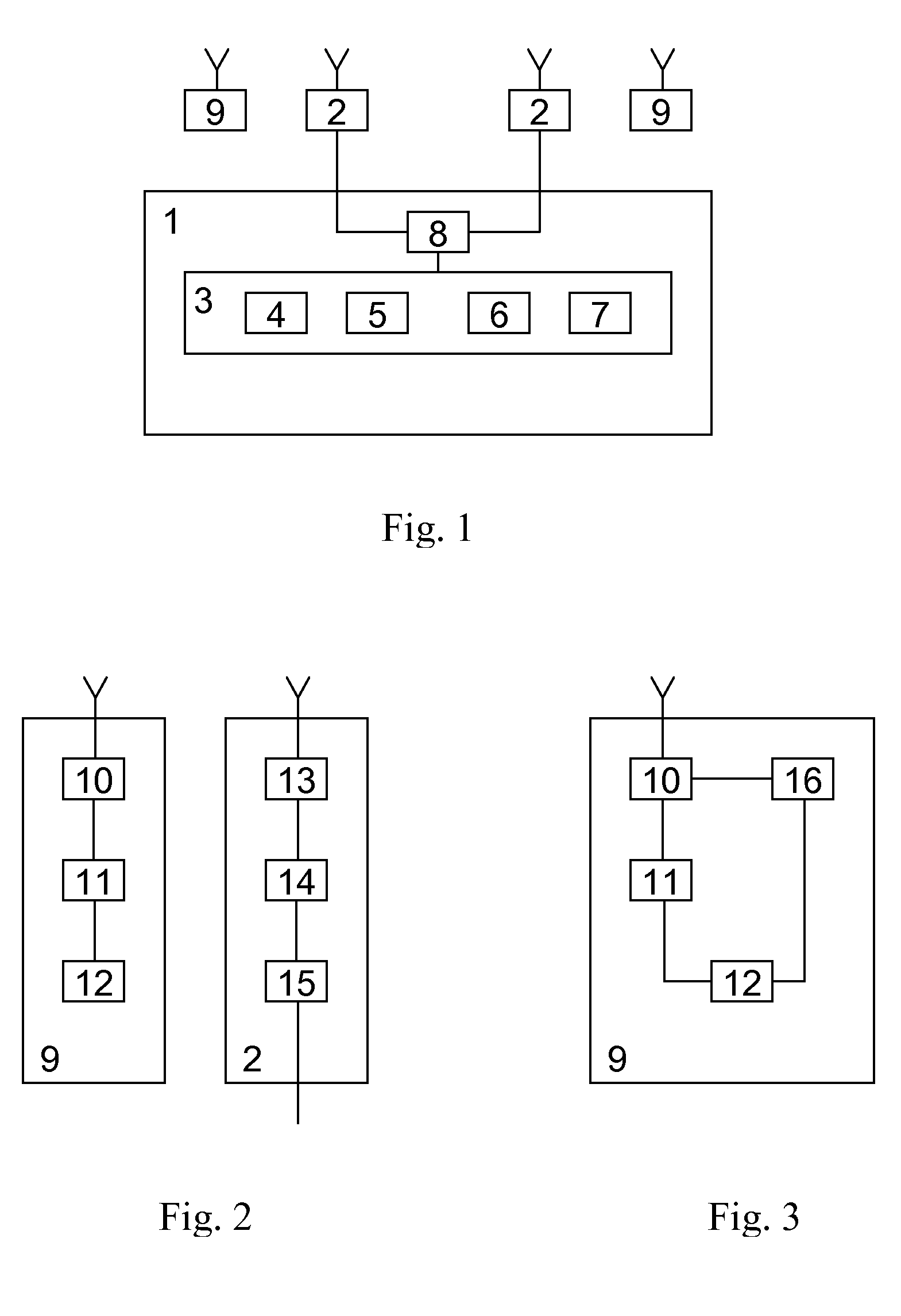
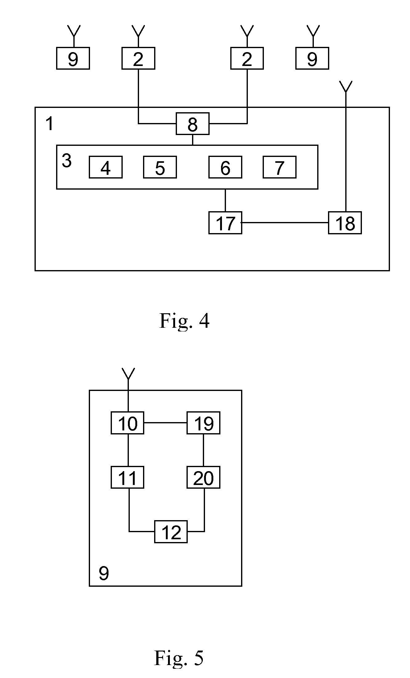
[0007]Essence of subscriber calling method (one variant) is in that at first message about called subscriber and called subscriber identifier are formed on called subscriber side; message signal is stored and identifier of device from which the message was received is defined and stored in telephone network; communication channel between telephone network and this device is cleared out; then a message about called subscriber and calling subscriber identifier is formed on calling subscriber side; message signal of calling subscriber is compared with previously stored signal about called subscriber and if the result is positive an identifier of device of calling subscriber is defined and communication channel between subscribers is established; if the result is negative a message about results of comparison is formed and transmitted to device of calling subscriber; at that at first message about called subscriber and his identifier forming is performed in one (secondary) terminal; mes...


PUM


Abstract

The invention can be used for designing a multi-purpose telephone unit for accessing to any communications and data transmission systems without limiting the system numbering capacity and with a free selection of a user's identification. In both variants, the inventive method consists in forming a message about a called subscriber on a (secondary) terminal, in transmitting it to another (primary) terminal, which has an identification tag in a telephone network, via a wireless telecommunication channel and, afterwards, in transmitting to the telephone network, wherein said message and the identification tag of the primary terminal from which it is received are stored. In the telephone network, the identification tags of the corresponding primary terminals are determined according to comparison results of information received from both calling and called subscribers, and a communication channel is established between said subscribers. The inventive system of communications devices comprises the telephone network provided with control equipment and the secondary and primary terminals on the calling and called subscribers. The secondary terminal comprises a control and information input and output unit, a conversion unit and a signal receiving transmitting unit using the wireless channel, the primary terminal comprises a signal receiving-transmitting unit using the wireless channel, a conversion unit and a network terminal which is connected via the communication channel to the control equipment of the telephone network which has individual or common with sad communication channel identification tag.

Description

FIELD OF THE INVENTION[0001]The invention refers to the field of telephony and can be used for designing a multi-purpose telephone unit for accessing to any communications and data transmission systems without limiting the system numbering capacity and with a free selection of a user's identification.BACKGROUND OF THE INVENTION[0002]There are a known the subscriber calling method and communication devices system (RU 2118062 C1, 4 Aug. 1997) that contains many general phone sets; telephone network of general use for receiving and transferring of specified packet data; great number of radiophones and base stations of general use; at that each of these stations is assigned to a specified coverage area and each of these stations controls digital radiophone, which is located in coverage area of the station; great number of local control units which are connected to appropriate base stations of general use; at that a local control unit stores information about base stations of general use...

Claims


Application Information

Patent Timeline
Patent Type & Authority Applications(United States)
IPC IPC(8): H04M1/56H04M3/50H04H20/00
CPCH04M3/42382H04M3/5322H04W76/021H04M2203/651H04M2201/18H04W76/11H04W8/18
Inventor RAKUSHIN, ALEXANDER STEPANOVICH
Owner MOLODCHENKO NIKOLAY ALEKSEEVICH
Learn More