

Injector Apparatus and Methods for Production of Nanostructures
a nanostructure and injector technology, applied in the direction of liquid chemical processes, thin-film liquid gas reaction processes, gas-gas reaction processes, etc., can solve the problems of limited growth of nanotubes and large catalysts that exhibit substantially no growth, so as to improve the growth process of carbon nanotubes, improve the growth process, and improve the effect of the flow ra
- Summary
- Abstract
- Description
- Claims
- Application Information
AI Technical Summary
Benefits of technology
Problems solved by technology
Method used
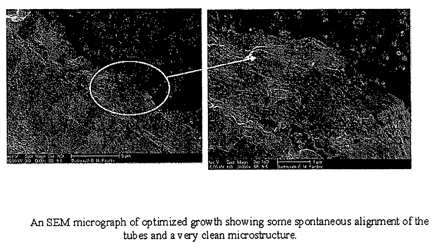
Image

Examples
experiment i
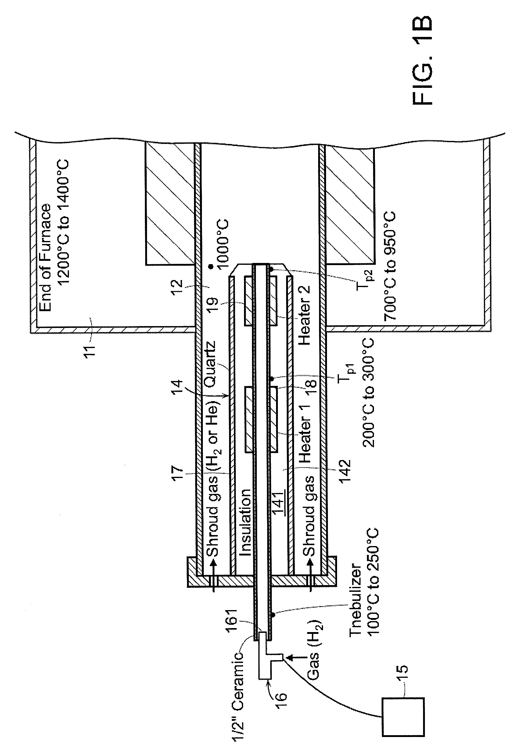
[0067]In one embodiment, the nature of the injector geometry, as well as the complex interaction of parameters can affect the strength and production efficiency of the nanostructures. In this experiment, yarn strength was monitored as a function of the thermal gradient at Tp2 and Tp1 (near the exit of the injector) for various concentrations of Ferrocene and Thiophene.
[0068]The results obtained for yarn strength as a function of thermal gradient are illustrated in FIG. 2. In particular, FIG. 2 shows a maximum in yarn strength as the injector thermal gradient is varied. Under lower than optimal thermal gradient conditions, there may be more time for the iron atoms generated by the decomposition of ferrocene to cluster before the clustering process is arrested by the sulfur provided by the decomposition of thiophene. This results in a larger diameter catalyst particles, which produces larger diameter and multi-walled nanotubes. The larger diameter tubes tend to be shorter, and therefo...
experiment ii
[0072]In this experiment, carbon source additives were used. Examples of additives include C60, C70 C72, C84 and C100. At a particular concentration, it was observed that the additives can enhance the catalyst nucleation and growth of the carbon nanotubes.
[0073]As can be seen in FIG. 6, when a carbon source additive is used, it can have a measurable effect on the RMB (radial breathing modes) / G ratio and the D / G ratio. Of interest, it does not appear that the amount of amorphous carbon is much affected. However, the presence of the carbon source additive can dramatically affect the catalyst nucleation and growth. In one embodiment, a concentration of a carbon additive at about 0.75 ppm appears to be optimal, as measured by the RBM / G ratio.
experiment iii
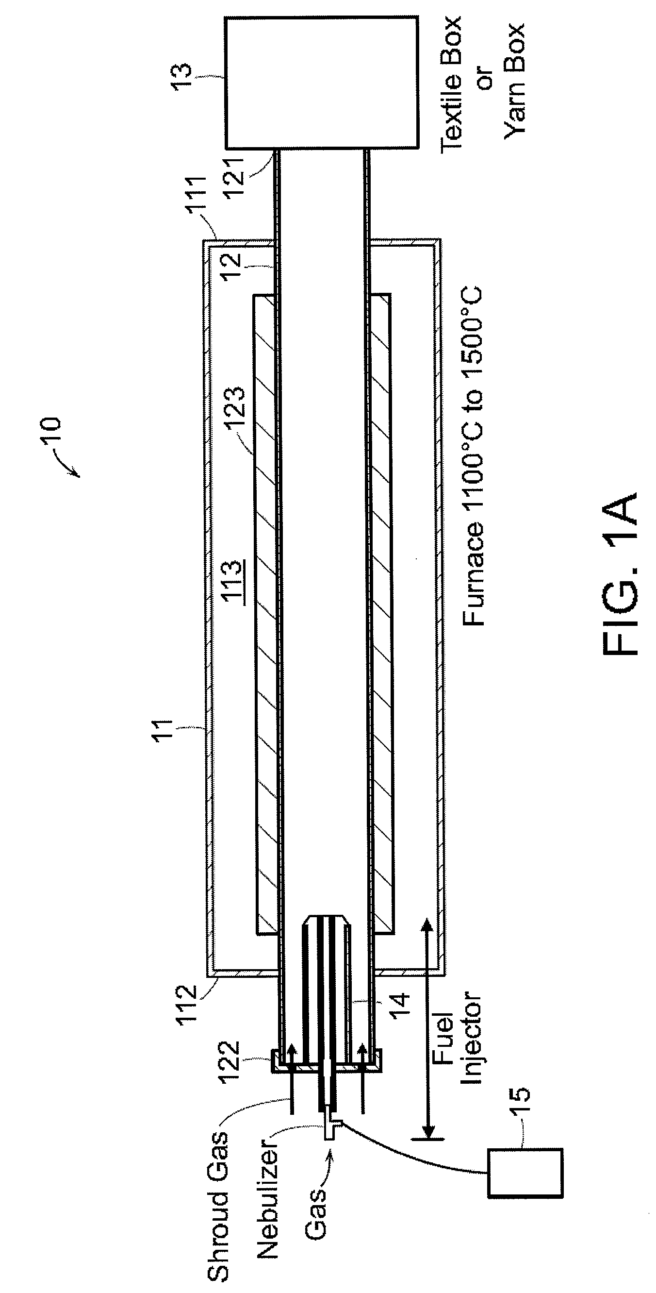
[0074]In this experiment, the flow of Hydrogen (H2) through the injector 14 was studied to determine whether such flow can be optimized to enhance growth and production efficiency in system 10 of the present invention.
[0075]In one embodiment, as shown in FIG. 7, the ratio of Hydrogen flow through the injector to the that in the reactor tube 12, when set at about 100× to about 110× the injection rate for a given set of other parameters, with about 104× being optimal, can enhance growth and production efficiency. It should be appreciated that variations in Hr reflect variations in the ratio of Hr / Hr. Moreover, this ratio can change for different fluid mixture make up.
[0076]The optimum ratio of Hydrogen flow can also be dependent upon the internal diameter (ID) of the injector tube. As illustrated in FIG. 8, the effect of Hydrogen flow through the injector on the RBMs can differ based on different IDs. The diameter IDs tested in connection with this particular experiment varied between...
PUM
| Property | Measurement | Unit |
|---|---|---|
| temperatures | aaaaa | aaaaa |
| diameter | aaaaa | aaaaa |
| density | aaaaa | aaaaa |
Abstract
Description
Claims
Application Information