Unit Cell Titanium Casting

a titanium casting and unit cell technology, applied in casting apparatus, metal-working apparatus, manufacturing tools, etc., can solve the problems of loss of substantial heat, increase costs, and time-consuming preparation of molding shells, so as to improve the efficiency of equipment, reduce pressure, and optimize the filling of complex geometries

Inactive Publication Date: 2018-02-15
TOPGOLF CALLAWAY BRANDS CORP
View PDF9 Cites 0 Cited by
  • Summary
  • Abstract
  • Description
  • Claims
  • Application Information

AI Technical Summary

Benefits of technology

[0010]Utilizing the two chamber casting system, one of the primary tenets is the use of a pressure differential in order to assist the evacuation of material from the crucible into the pattern mold. In order to truly optimize the filling of complex geometries, the physical properties of resulting parts, and the efficiency of the equipment, it is beneficial to vary the pressure differential utilized during the casting sequence. Optimally, the beginning of the cycle will have a minimal pressure differential between the outer chamber (containing the crucible) and the inner chamber (containing the pattern mold). This pressure differential is achieved through the use of a vacuum (to remove Oxygen and reduce pressure) and Argon (to replace any remaining Oxygen and increase pressure). Immediately prior to crucible evacuation the pressure in the inner chamber would be decreased; this will allow for additional pressure-assisted transition in order to allow the filling of complex geometries, while minimizing turbulent flow of molten Titanium, and also minimizing overall equipment cycle times.

Problems solved by technology

Vacuum induction smelting and vacuum electric arc smelting require the use of a water-cooled copper crucible which results in the loss of substantial heat.
Furthermore, the preparation of the molding shell is very complex and time consuming, which adds to the costs.
The molten titanium liquid will come into direct contact with water if the crucible cracks, resulting in a fierce reaction, or even explosion, which poses a great threat to production safety.

Method used


Image

  • Unit Cell Titanium Casting
  • Unit Cell Titanium Casting
  • Unit Cell Titanium Casting

Examples


Embodiment Construction

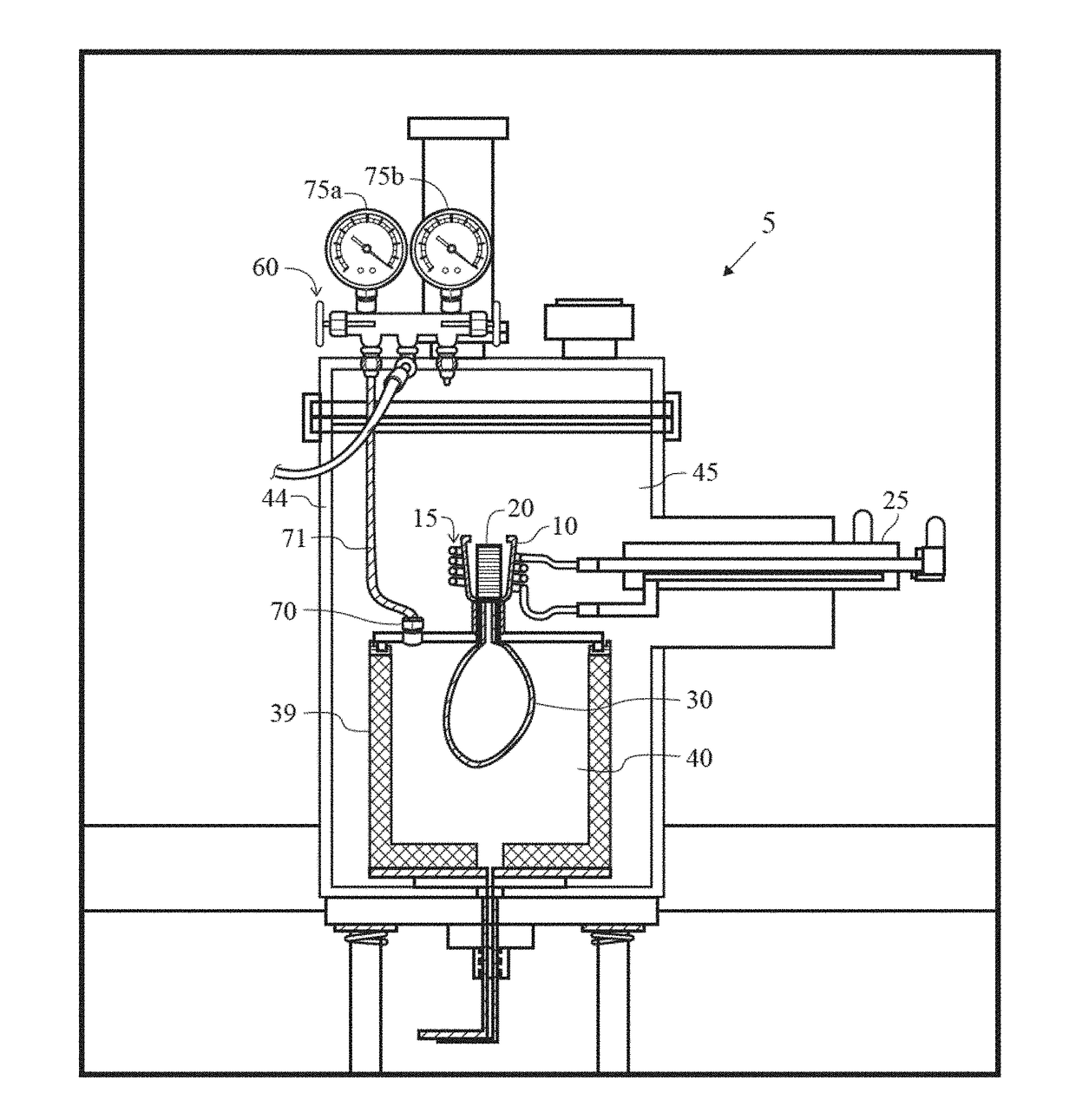
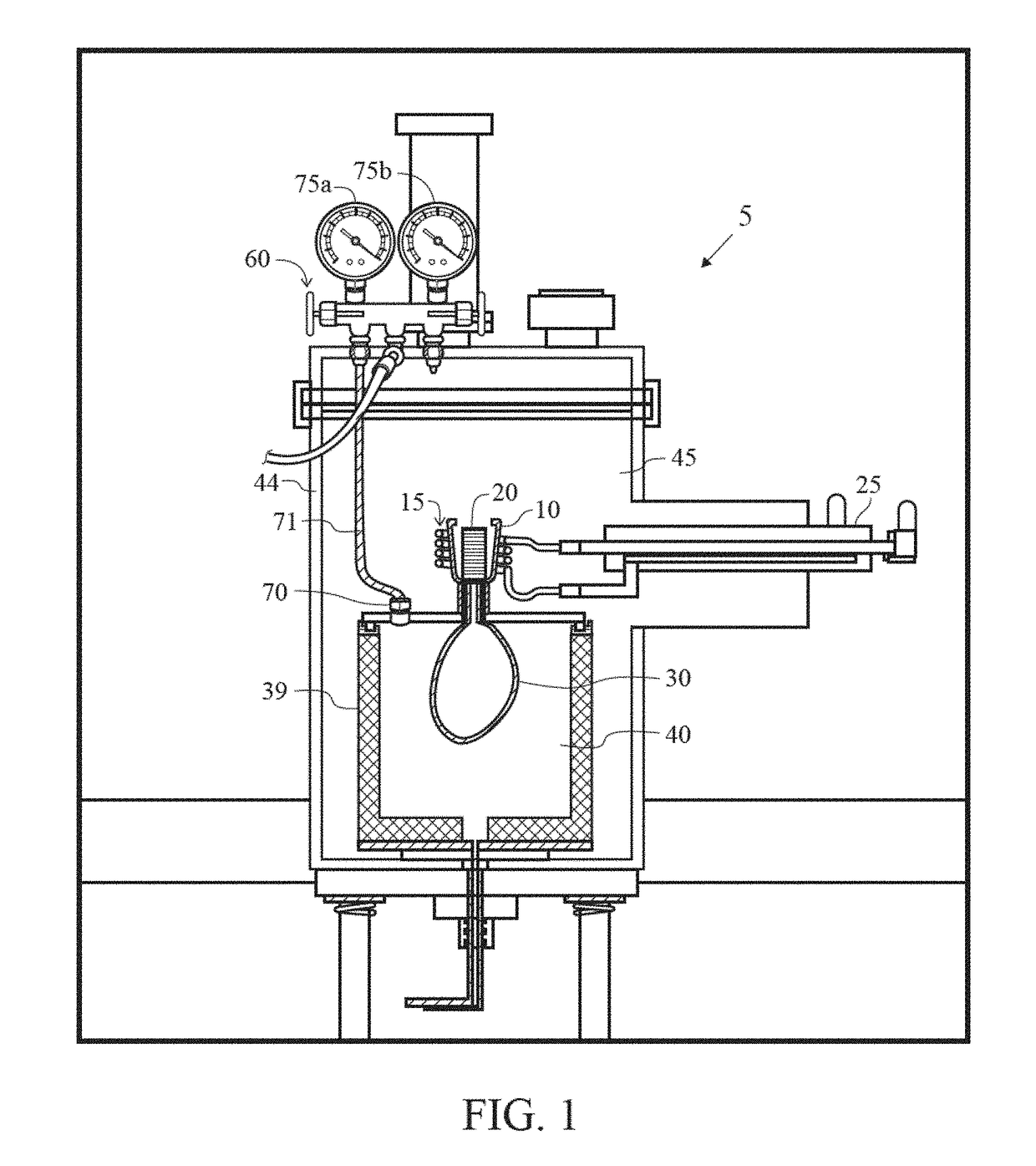
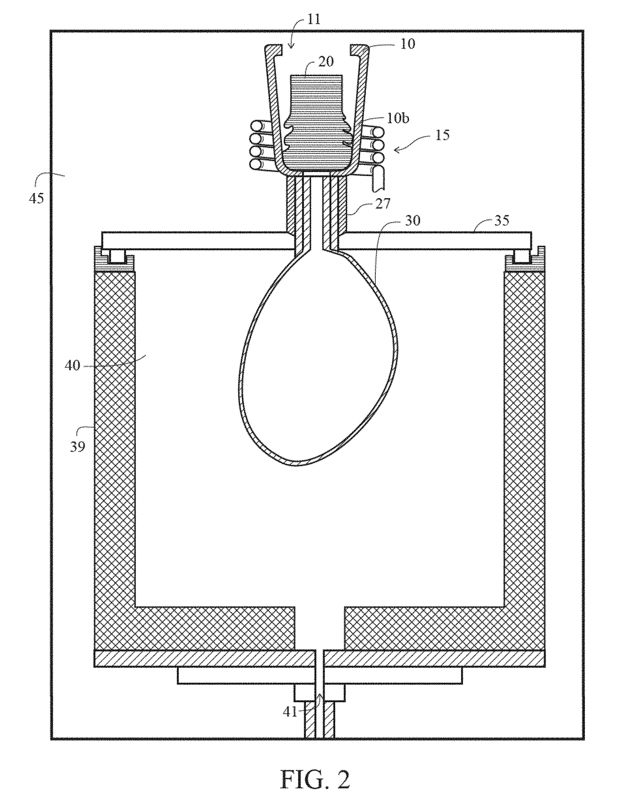
[0038]During the casting process it is critical to ensure that the material be heated sufficiently and consistently in order to ensure proper flow into the pattern mold. Especially with the use of a bottom-fed / gravity flow system, having the ability to precisely control the pour time will allow for optimum material heating ensuring desired material properties in the finished part. In order to achieve this a chill plate should be utilized which would help to definitively control the time that the molten material would transition to the pattern mold. The chill plate would be in the shape of a ring, with an opening centered on the opening of the ceramic crucible where the material is being melted. The plate itself would be cooled during melting and then at the optimal pour time, the cooling would be turned off. With the cooling, the seal melts through and the material is evacuated into the pattern mold. The use of this feature will allow for precise evacuation times providing consisten...


PUM

PropertyMeasurementUnit
pressureaaaaaaaaaa
pressureaaaaaaaaaa
atmospheric pressureaaaaaaaaaa

Abstract

A system (5) and method (800) for unit cell casting of titanium or titanium-alloys is disclosed herein. The system (5) comprises an external chamber (45), a crucible (10) positioned within the external chamber (45), an induction coil (15) positioned around the crucible, an internal chamber (40) positioned within the external chamber (45), and a mold (30) positioned within the internal chamber (40). The external chamber (45) is evacuated and a pressurized gas is injected into the evacuated external chamber (45) to create a pressurized external chamber (45). An ingot (20) is melted within the crucible utilizing induction heating generated by the induction coil (15). The internal chamber (40) is evacuated to create an evacuated internal chamber (40). The titanium alloy material of the ingot (20) is completely transferred into the mold (30) from the crucible (10) using a pressure differential created between the external chamber (45) and the internal chamber (40).

Description

CROSS REFERENCES TO RELATED APPLICATIONS[0001]The present application claims priority to U.S. Provisional Patent Application No. 62 / 374,665, filed on Aug. 12, 2016, which is hereby incorporated by reference in its entirety.STATEMENT REGARDING FEDERALLY SPONSORED RESEARCH OR DEVELOPMENT[0002]Not ApplicableBACKGROUND OF THE INVENTIONField of the Invention[0003]The present invention relates to precision titanium casting. More specifically, the present invention relates to an apparatus and method for precision titanium casting utilizing induction heating.Description of the Related Art[0004]Various methods of titanium casting are well-known. One such method is investment casting which involves a lost wax procedure.[0005]Vacuum electric arc smelting is another method in which a titanium ingot is melted by substantial heat generated by mutual discharging in a high current state by respectively using a titanium ingot crucible and a water-cooled copper crucible as a positive electrode and a ...

Claims


Application Information

Patent Timeline
Patent Type & Authority Applications(United States)
IPC IPC(8): B22D15/00B22D27/00B22D46/00B22D18/06B22D21/06
CPCB22D15/00B22D18/06B22D27/003B22D46/00B22D21/06B22D18/04B22D21/005
Inventor PARAISO, JANSMITH, NORM
Owner TOPGOLF CALLAWAY BRANDS CORP
Why Eureka
Try Eureka