Electrical contact assembly including a sleeve member

a technology of electrical contact and sleeve, which is applied in the direction of insulated conductors, power cables, cables, etc., can solve the problems of corroding easily, brittleness, and hermetic sealing of the core of the contact assembly

Inactive Publication Date: 2009-05-07
TRI STAR ELECTRONICS INT
View PDF11 Cites 25 Cited by
  • Summary
  • Abstract
  • Description
  • Claims
  • Application Information

AI Technical Summary

Benefits of technology

[0028]A detent engaging element and a detent element are provided in certain embodiments as a positioning aid during the assembly of the contact assembly. According to certain embodiments, these elements are engaged after continuity crimping has occurred. The engagement of these elements holds the tubular sleeve member at a desired location relative to the tubular member as the sleeve deformation step is initiated. A worker can feel and/or hear when these two elements engage with one another. By pulling on the contact member and the tubular sleeve member in a direction to disengage them a worker can determine whether the detent and detent engaging elements are still engaged. This quick and easy check, after the wire is manipulat

Problems solved by technology

Aluminum, however, corrodes easily, and it is much more brittle than some of the other metals such as, for example, copper or silver.
Wires composed of other metals may require hermetic sealing of their cores because of exposure to corrosive environments during use.
If a worker is not familiar with both types of contacts, or becomes confused, there is a significant risk that an electrical contact that is designed for one type of core will be a

Method used


Image

  • Electrical contact assembly including a sleeve member
  • Electrical contact assembly including a sleeve member
  • Electrical contact assembly including a sleeve member

Examples


Embodiment Construction

[0057]Referring now to the drawings wherein like reference numerals designate identical or corresponding parts throughout the several views. It is to be understood that the drawings are diagrammatic and schematic representations of various embodiments of the invention, and are not to be construed as limiting the invention in any way. The use of words and phrases herein with reference to specific embodiments is not intended to limit the meanings of such words and phrases to those specific embodiments. Words and phrases herein are intended to have their ordinary meanings, unless a specific definition is set forth at length herein.

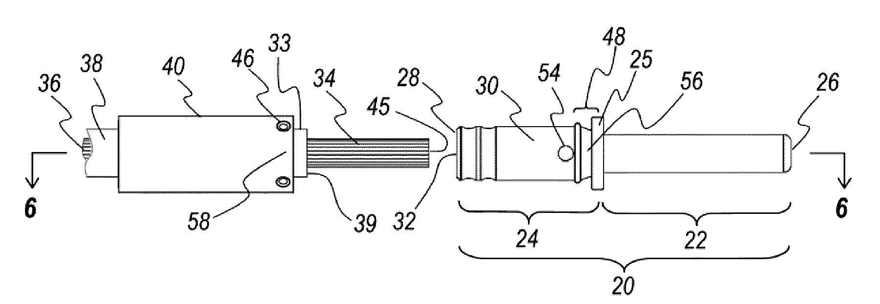
[0058]Referring particularly to the drawings, there is illustrated generally at 20 in FIG. 1 an exploded view including a crimpable and sealable contact assembly generally in alignment with an electrically insulated wire 38. The contact assembly includes an electrical contact member 20 and a barrel portion 24 that are generally aligned along a common axis bet...


PUM

PropertyMeasurementUnit
Electrical conductivityaaaaaaaaaa
Lengthaaaaaaaaaa
Transparencyaaaaaaaaaa

Abstract

A low cost crimpable and sealable contact assembly including a contact member and a tubular sleeve member. The contact member is capable of being manually continuity crimped to a tip of an electrically conductive core of an electrically insulated wire. The tubular sleeve member is then deformed to hermetically seal it to the insulation on the wire, and the contact member. The hermetic seal protects the core from corrosion. This hermetic seal is particularly important where the core comprises aluminum. Separating the crimping and sealing into separate operations permits them to be performed manually. The sleeve member may be comprised of polymeric material, or it may be metallic. The metallic embodiments may be mechanically or electromagnetically deformed. The polymeric sleeve members may, in addition, be heat shrunk.

Description

RELATED APPLICATIONS[0001]This application claims the benefit of U.S. Provisional Application No. 60 / 915,398, filed May 1, 2007BACKGROUND OF THE INVENTION[0002]1. Field of the Invention[0003]The invention relates in general to methods and devices, embodiments of which include electrical contacts that are deformable into electrical continuity and hermetic sealing with an insulated wire, and, more particularly, certain embodiments of the present invention relate to electrical contact assemblies including a deformable sleeve for forming a hermetic seal between a closed barrel electrical contact and an insulated electrical wire to which the electrical contact is mounted.[0004]2. Description of the Prior Art[0005]Electrical contacts are conventionally provided in lieu of solder joints for purposes of providing electrical continuity between the electrically conductive core of an insulated electrical wire and an electrical bus or other device to which it is desired to attach the core. The ...

Claims


Application Information

Patent Timeline
IPC IPC(8): H01R4/10B23P19/00
CPCH01R4/20H01R4/62Y10T29/53235H01R43/048Y10S439/932H01R4/72
Inventor KERNER, ALEX
Owner TRI STAR ELECTRONICS INT
Why Eureka
Try Eureka