
Method and system for automatic uplink power control in wireless communication

a wireless communication and power control technology, applied in wireless communication, power management, sustainable buildings, etc., can solve the problems of increasing the difficulty of maintaining system stability in a highly dynamic link quality environment, affecting the reliability of the transmission system, so as to reduce or eliminate planned power level changes, improve signal quality, and improve the effect of signal quality

Inactive Publication Date: 2009-05-07
VIASAT INC
View PDF6 Cites 9 Cited by
  • Summary
  • Abstract
  • Description
  • Claims
  • Application Information

AI Technical Summary

Benefits of technology

[0018]In a specific embodiment of a system according to the invention, the system implements an embedded control method comprising three elements: code for a “fast attackalgorithm that is responsive to a sequence of non-continuous signal reports indicative of degrading link quality; code for a “slow decay” algorithm that is operative to maintain a current link margin for an interval during which non-continuous signal reports indicative of improved signal quality are confirmed; and code for a “time-deratingalgorithm that reduces or eliminates planned power level changes that occur too soon after a previous change was implemented.

Problems solved by technology

A power amplifier can transmit information modulated onto a signal carrier over a distance via communication channel subject to uncontrolled propagation to a remote receiver.
The emergence of Ka-band (30 GHz) band for communication using geo-synchronous satellites poses a fundamentally more difficult problem.
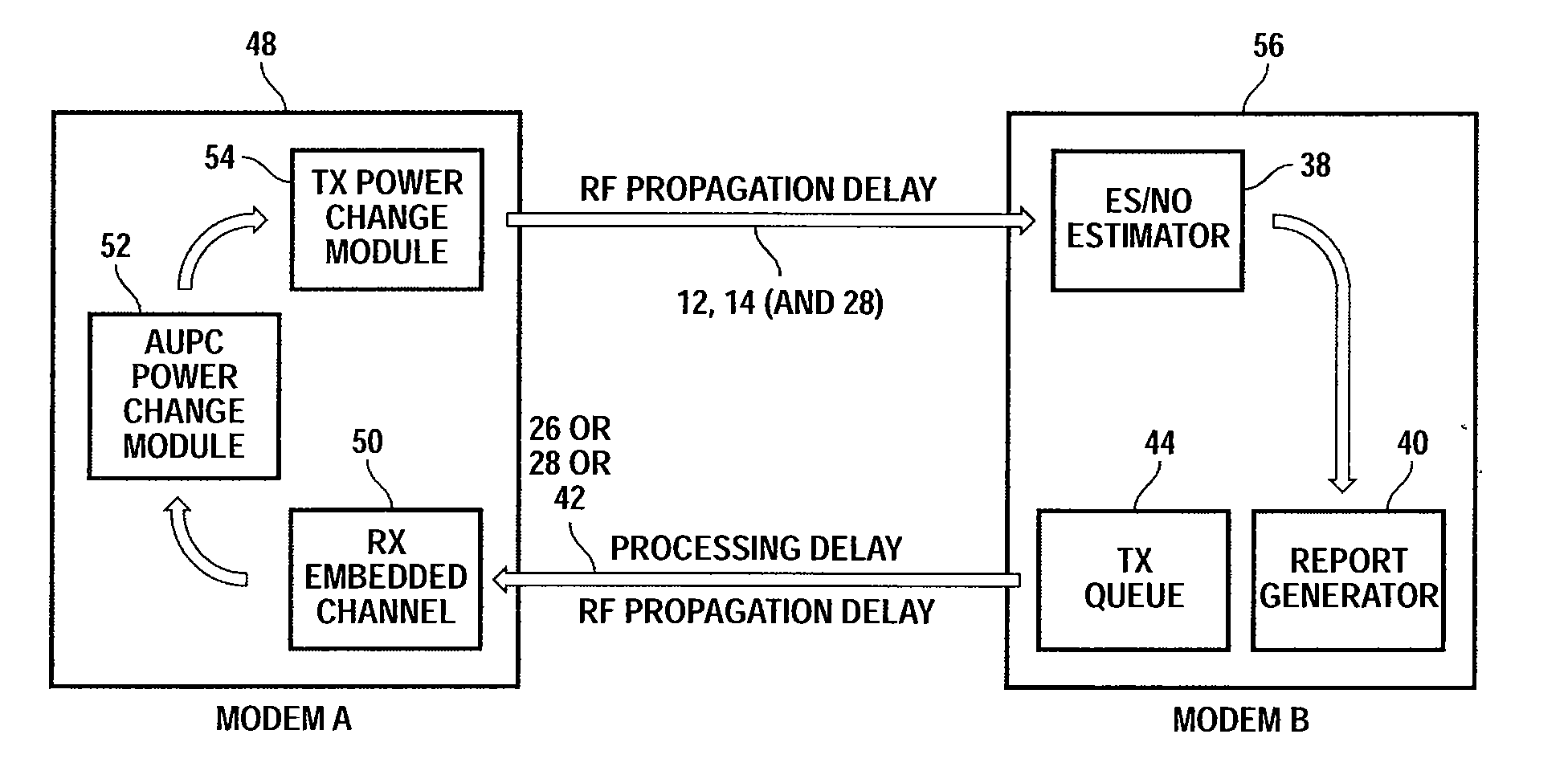
Given a typical 260 ms end-to-end RF propagation delay, plus processing delays on the order of half a second, the signal quality reports are found to be correlated with previous power changes, increasing the problem of maintaining system stability in a highly dynamic link quality environment.
In other words, the control system controlling signal power level can be caused to oscillate uncontrollably.

Method used


Image

  • Method and system for automatic uplink power control in wireless communication
  • Method and system for automatic uplink power control in wireless communication
  • Method and system for automatic uplink power control in wireless communication

Examples


Embodiment Construction

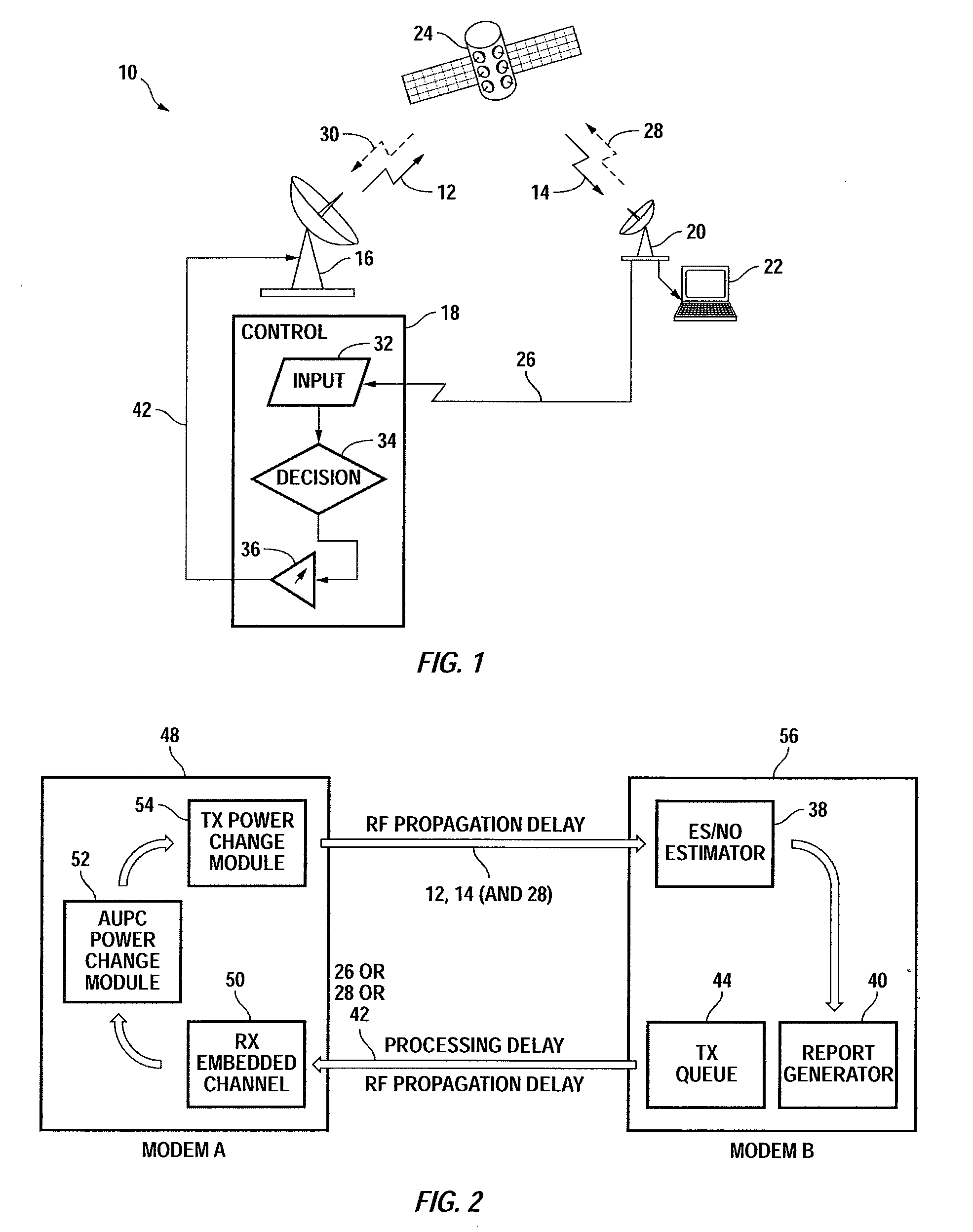
[0025]FIG. 1 illustrates a communication system 10 having a communication uplink 12, 14 between a local transmitter 16 and control system 18 and a remote receiver 20 and user terminal 22 via a satellite 24 providing a relay with a return channel 26 or 28, 30 for carrying signal quality reports. The control system 18 according to the invention is provided for adjusting transmit power. The control system 18 includes an input element 32 for receiving and interpreting signal quality reports obtained at the remote receiver(s) 20 about signals via the link 12, 14 originating from the local transmitter 16. The control system 18 includes decision analysis tools 34 according to the invention and a power adjustment message output 36 to inform the transmitter 16 of the need to adjust transmit power of the transmitter 16. This is a feedback control system impacted by uncontrolled delays in processing and propagation, as for example when the length of the propagation path on the link 12, 14 is c...


PUM


Abstract

Automatic control of transmitted power of a transmitted signal at a local transmitter in response to intermittent signal quality reports from a remote receiver about a received communication signal originating as the transmitted communication signal is provided by distinguishing between improving link conditions and degrading link conditions and at least derating a scheduled signal power change if there are changes in the signal quality reports, such as if the power change is scheduled to occur too soon after a previous signal power change. A fast attack power increase and slow decay power decrease may also be employed. The method is designed to maintain signal quality (e.g. distant Es / No) in the presence of these variations and uncertainties, for time-varying link conditions that have a fade rate range from less than 0.01 dB / s to more than 1 dB / s.

Description

CROSS-REFERENCES TO RELATED APPLICATIONS[0001]The present application claims benefit under 35 USC 119(e) of U.S. provisional Application No. 60 / 984,989, filed on Nov. 2, 2008, entitled “Method for Power Control in Wireless Communications,” the content of which is incorporated herein by reference in its entirety.STATEMENT AS TO RIGHTS TO INVENTIONS MADE UNDER FEDERALLY SPONSORED RESEARCH OR DEVELOPMENT[0002]Not ApplicableREFERENCE TO A “SEQUENCE LISTING,” A TABLE, OR A COMPUTER PROGRAM LISTING APPENDIX SUBMITTED ON A COMPACT DISK[0003]Not ApplicableBACKGROUND OF THE INVENTION[0004]This invention relates to control of link performance through a communications link, typically a satellite, to maximize efficiency of use of valuable channel resources while assuring adequate signal reception quality. In particular, the invention relates to implementation of link performance control in an enhanced bandwidth efficient modem for transponded satellite communication.[0005]In order to assist in ...

Claims


Application Information

Patent Timeline
IPC IPC(8): H04B7/005H04B17/40
CPCH04W52/146H04W52/228Y02B60/50H04W52/247H04W52/241
Inventor DAVIS, BENJAMIN MICHAELPAI, YULINCOLN, ANDREW JOHN
Owner VIASAT INC
Learn More