Method of labelling swappable pins for integrated circuit pattern matching

a technology of integrated circuit and pattern matching, applied in the direction of specific program execution arrangements, program control, resources, etc., can solve the problems of design analysis not having the benefit of a known detailed reference, other differences between electrically identical circuit fragments may not be detected, and patent infringement and/or licensing issues, etc., to achieve the effect of increasing computational complexity

Active Publication Date: 2009-05-07
TECHINSIGHTS
View PDF2 Cites 4 Cited by
  • Summary
  • Abstract
  • Description
  • Claims
  • Application Information

AI Technical Summary

Benefits of technology

[0025]An embodiment of the present invention seeks to provide a simple but novel regime for re-labelling swappable pins that permits swappability information to be maintained without significantly increasing computational complexity and is conducive to inexact pattern matching for the purposes of developing more complex logical processing blocks from elementary components in design analysis.

Problems solved by technology

Moreover, the information may constitute evidence of copying that may give rise to patent infringement and / or licensing issues.
Unlike testing and verification of a known design, design analysis typically does not have the benefit of a known detailed reference.
However, such method assumes that each sub-circuit has an identical layout, which may not always be the case.
Moreover, much of the modern IC design is done automatically by auto-routing, with the electrical components being positioned in a space-efficient manner, which may not necessarily constitute a logical or even a visually appealing manner.
However, other differences between electrically identical circuit fragments may not be detected by inexact pattern-matching in isolation.
Some components, however, have much more complex swappability.
Those having ordinary skill in this art will appreciate that as simpler components, such as gates, are built up into more complex components, such as flip-flops, adders and processors, as routinely occurs in ICs, the level of complexity of the swappability of nodes may similarly increase.

Method used


Image

  • Method of labelling swappable pins for integrated circuit pattern matching
  • Method of labelling swappable pins for integrated circuit pattern matching
  • Method of labelling swappable pins for integrated circuit pattern matching

Examples


Embodiment Construction

[0034]The invention will be described for the purposes of illustration only in connection with certain embodiments; however, it is to be understood that other objects and advantages of the present invention will be made apparent by the following description of the drawings according to the present invention. While a preferred embodiment is disclosed, this is not intended to be limiting. Rather, the general principles set forth herein are considered to be merely illustrative of the scope of the present invention and it is to be further understood that numerous changes may be made without straying from the scope of the present invention.

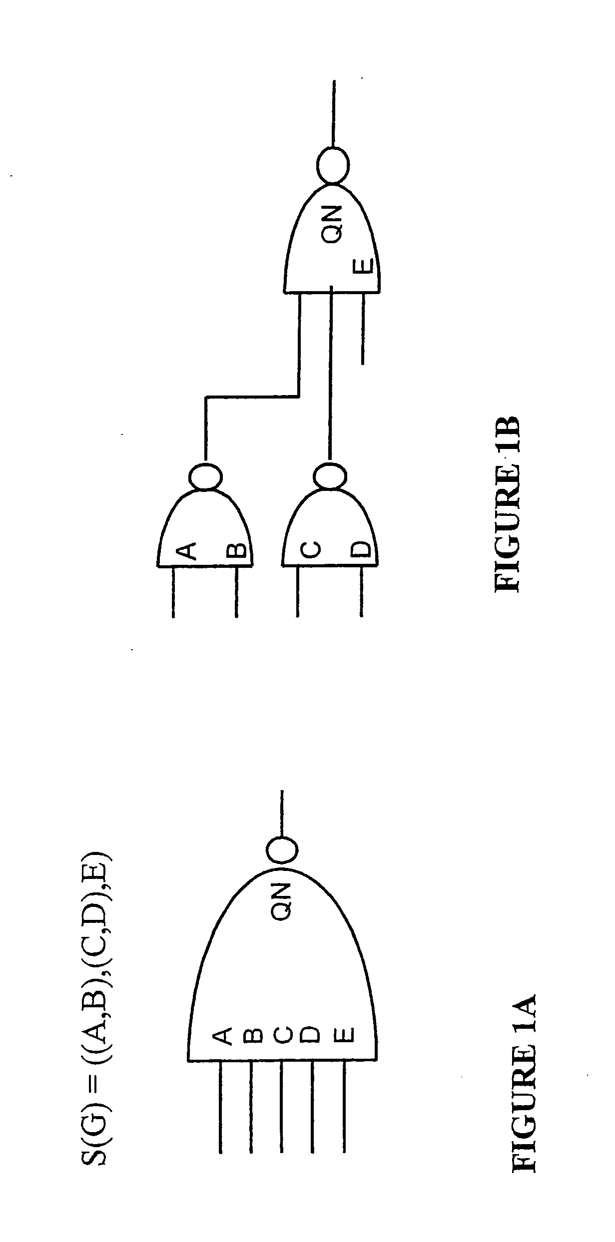
[0035]At the outset, in order to discuss complex swappability, it may be helpful to introduce a notational shorthand, in which swappable inputs are surrounded by round parentheses “( )” while inputs that are not interchangeable are surrounded by square brackets “[].” Thus, for example, a swappability relation S(G) for a gate G, expressed as

S(G)=((A, B)...


PUM


Abstract

The present invention seeks to provide a simple, but novel regime, for re-labelling swappable pins that permits swappability information to be maintained without significantly increasing computational complexity and is conducive to inexact pattern matching for the purposes of developing more complex logical processing blocks from elementary components in design analysis. The method comprises a recursive application of a simple labelling procedure. This method is repeated recursively until all gate instances in the circuit fragment have been assigned a swappability number.

Description

FIELD OF THE INVENTION[0001]The present invention relates to integrated circuit network analysis and more particularly to methods for modelling and recording complex node interchangeability properties.BACKGROUND TO THE INVENTION[0002]In the intensely competitive field of microelectronics, detailed analysis of a semiconductor integrated circuit (IC) product may provide valuable information as to how a particular technical problem was solved, overall strengths and weaknesses of a design approach and the like. Such information may be used to make decisions relating to market positioning, future designs and new product development. Moreover, the information may constitute evidence of copying that may give rise to patent infringement and / or licensing issues.[0003]Typically, such information is obtained from analysis of the product by means of circuit extraction or reverse engineering, as well as functional analysis and other technical means. At the core of such activity lies the process ...

Claims


Application Information

Patent Timeline
Patent Type & Authority Applications(United States)
IPC IPC(8): G06F17/50G06Q10/06
CPCG06F17/5081G06F17/5022G06F30/33G06F30/398
Inventor SOURJKO, SERGEIZAVADSKY, VYACHESLAV
Owner TECHINSIGHTS
Why Eureka
Try Eureka