Double DX Hydronic System

a hydronic system and double dx technology, applied in the direction of sustainable buildings, heating types, lighting and heating apparatus, etc., can solve the problems of increasing the power draw of the compressor, reducing reducing the power consumption of the compressor, so as to maximize the overall system operational efficiency, avoid water pumping, and minimize the power consumption required to operate the system

Inactive Publication Date: 2009-05-14
EARTH TO AIR SYST
View PDF99 Cites 10 Cited by
  • Summary
  • Abstract
  • Description
  • Claims
  • Application Information

AI Technical Summary

Benefits of technology

[0024]Finally, a respective liquid circulator pump may be positioned within each respective secondary fluid line servicing each respective secondary DX sub-system interior heat exchanger. The pump may operate only when the secondary respective DX compressor box was on, thereby further maximizing overall system operational efficiencies. By providing smaller pumps dedicated to each secondary DX sub-system, the use of a single, larger, more power consuming, water pump is avoided, and the pumps may operate only when fluid circulation is required in the associated sub-system. Consequently, power consumption required to operate the system is minimized.

Problems solved by technology

(sometimes even below 52 degrees if the return air in the interior air handler is below 70 degrees F., which is not normally the case), the interior heat exchanger tubing is more susceptible to developing frost, which decreases system operational efficiencies.
Conversely, supply fluid temperatures above 80 degrees F. increase the head refrigerant pressures, which increases the power draw of the compressor and decreases system operational efficiencies.
Based on testing, however, it has been found that supply fluid temperatures above 68 degrees F. produces excessive refrigerant head pressure, which increases the power draw of the compressor, thereby decreasing system operational efficiencies.

Method used


Image

  • Double DX Hydronic System
  • Double DX Hydronic System

Examples


Embodiment Construction

[0028]The following detailed description is of the best presently contemplated mode of carrying out the subject matter disclosed herein. The description is not intended in a limiting sense, and is made solely for the purpose of illustrating the general principles of this subject matter. The various features and advantages of the present disclosure may be more readily understood with reference to the following detailed description taken in conjunction with the accompanying drawings.

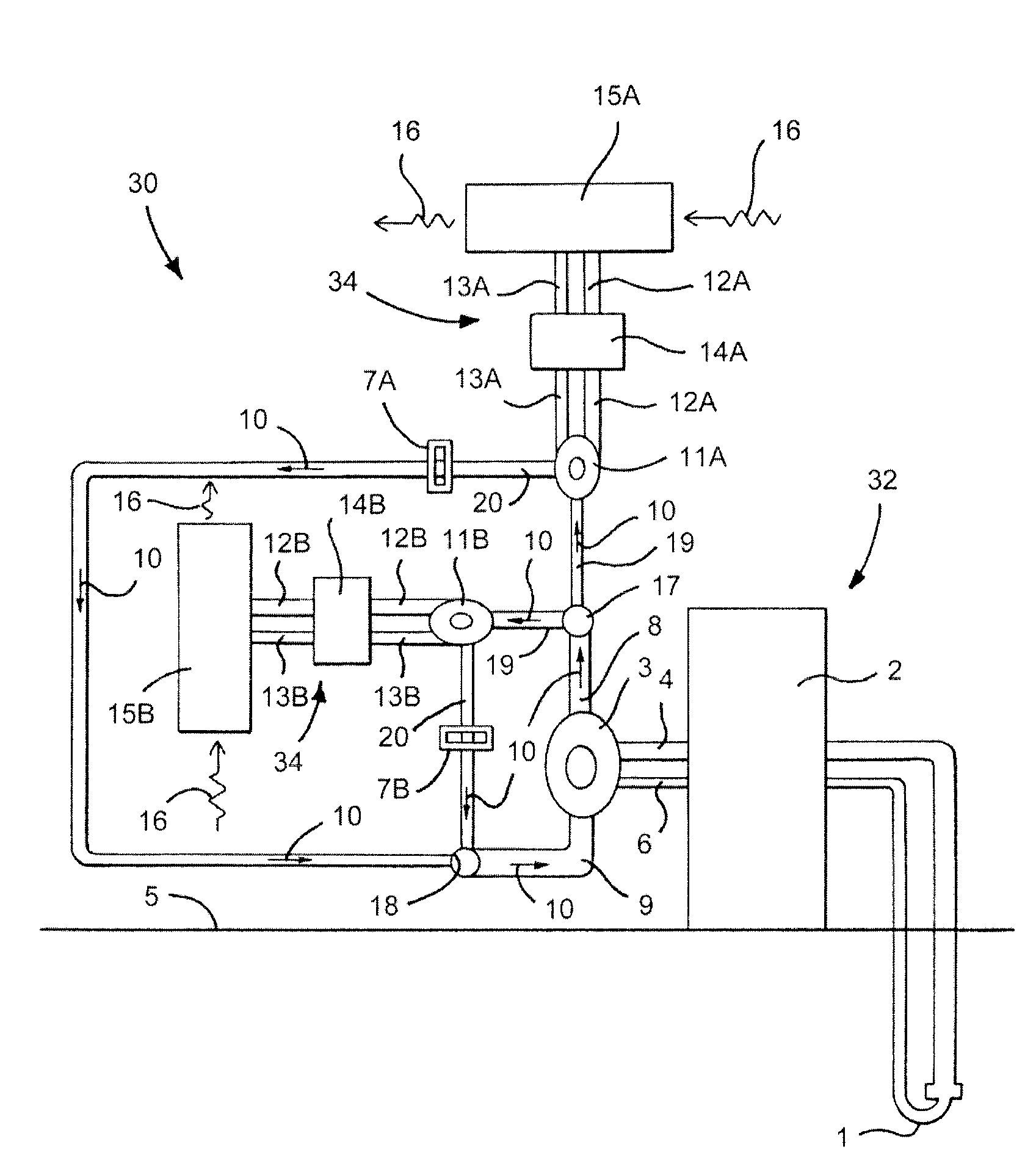
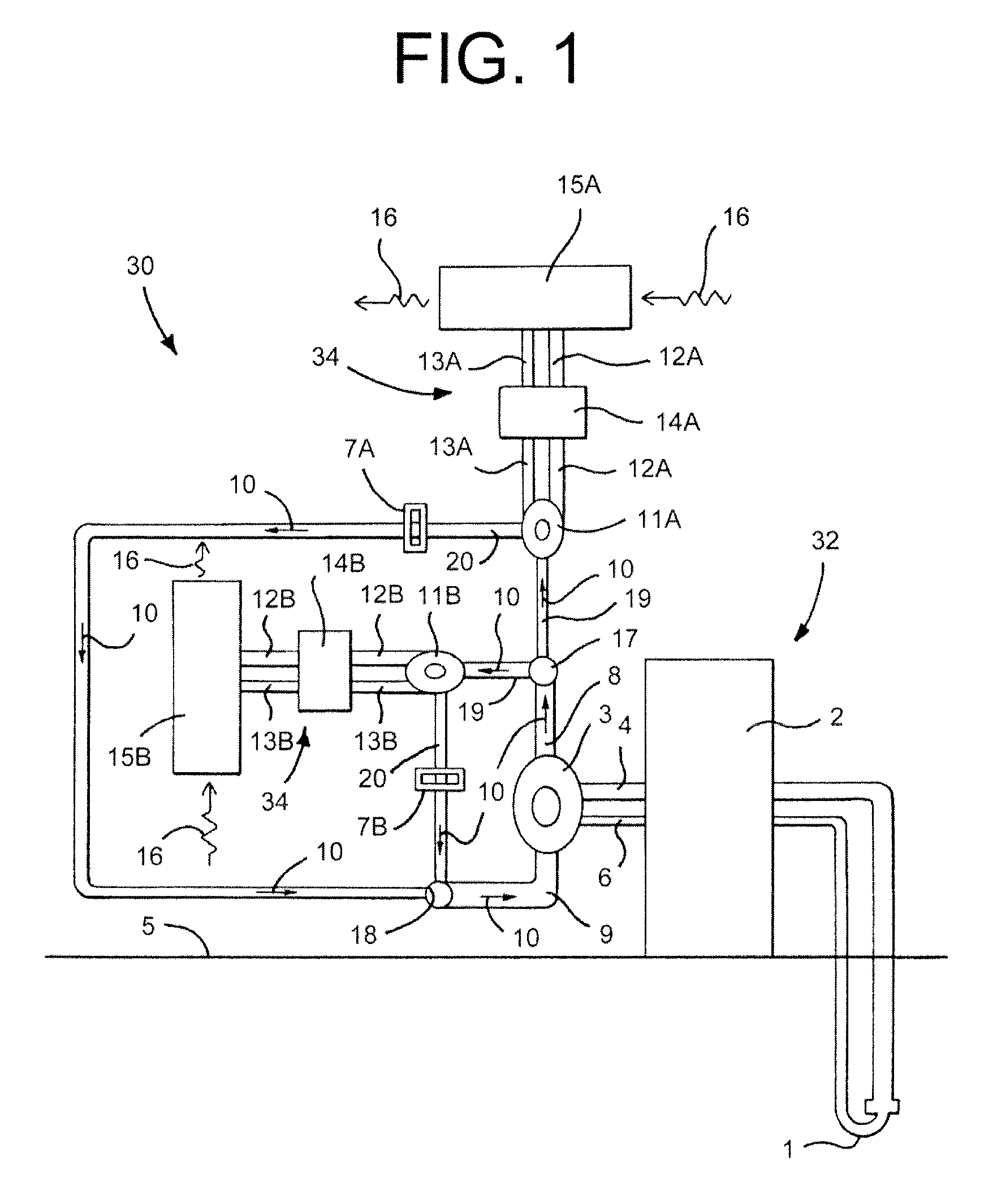
[0029]FIG. 1 shows a double DX hydronic system 30 capable of simultaneously heating and cooling separate control media, such as interior air (not shown). The system 30 may generally include a primary DX sub-system 32 and at least two secondary DX sub-systems 34, with unique additional features, as more fully described herein.

[0030]The primary DX sub-system 32 may include a primary heat exchanger 1 located below a surface 5 of the ground or water. Accordingly, the primary heat exchanger is alternatively ref...


PUM


Abstract

A double DX hydronic heating/cooling system includes a primary DX system for maintaining a primary interior fluid loop at a desired temperature range. Secondary DX sub-systems are operatively coupled to the primary interior fluid loop and are operable in either a heating mode or a cooling mode to provide independent control of interior air temperature in different spaces. Each sub-system includes a dedicated water pump to minimize power requirements for the system.

Description

FIELD OF THE DISCLOSURE[0001]The present disclosure relates to geothermal direct exchange (“DX”) heating / cooling systems, which are also commonly referred to as “direct exchange” or “direct expansion” heating / cooling systems.BACKGROUND OF THE DISCLOSURE[0002]Geothermal ground source / water source heat exchange systems typically include closed loops of tubing that are buried in the ground, or submerged in a body of water. Fluid is circulated through the loops of tubing so that the fluid either absorbs heat from or rejects heat into the naturally occurring geothermal mass and / or water surrounding the tubing. The ends of the tubing loop extend to the surface and are fluidly coupled to an interior air heat exchanger. The naturally warmed or cooled fluid is circulated through the interior air heat exchanger to warm or cool an interior space.[0003]Common and older design geothermal water-source heating / cooling systems typically have a pump for circulating a fluid comprised of water, or wat...

Claims


Application Information

Patent Timeline
Patent Type & Authority Applications(United States)
IPC IPC(8): F24J3/08
CPCF24D3/18F24D2200/11Y02B30/12Y02B10/40Y02E10/125F24J3/083F24T10/15Y02E10/10
Inventor WIGGS, B. RYLAND
Owner EARTH TO AIR SYST
Why Eureka
Try Eureka