Motor Drive Device and Motor Drive Device Control Method

a technology of motor drive device and control method, which is applied in the direction of motor/generator/converter stopper, process and machine control, etc., can solve the problems of limiting the enhancement of system efficiency, and achieve the effect of improving system efficiency in the motor control

a technology of motor drive device and control method, which is applied in the direction of motor/generator/converter stopper, process and machine control, etc., can solve the problems of limiting the enhancement of system efficiency, and achieve the effect of improving system efficiency in the motor control

US20090121669A1Active Publication Date: 2009-05-14DENSO CORP

Image

  • Motor Drive Device and Motor Drive Device Control Method
  • Motor Drive Device and Motor Drive Device Control Method
  • Motor Drive Device and Motor Drive Device Control Method

Examples


Embodiment Construction

[0027]An embodiment of the present invention will be specifically described below with reference to the drawings. The same or corresponding portions in the drawings are provided with the same reference numerals to avoid repeated description of the portions.

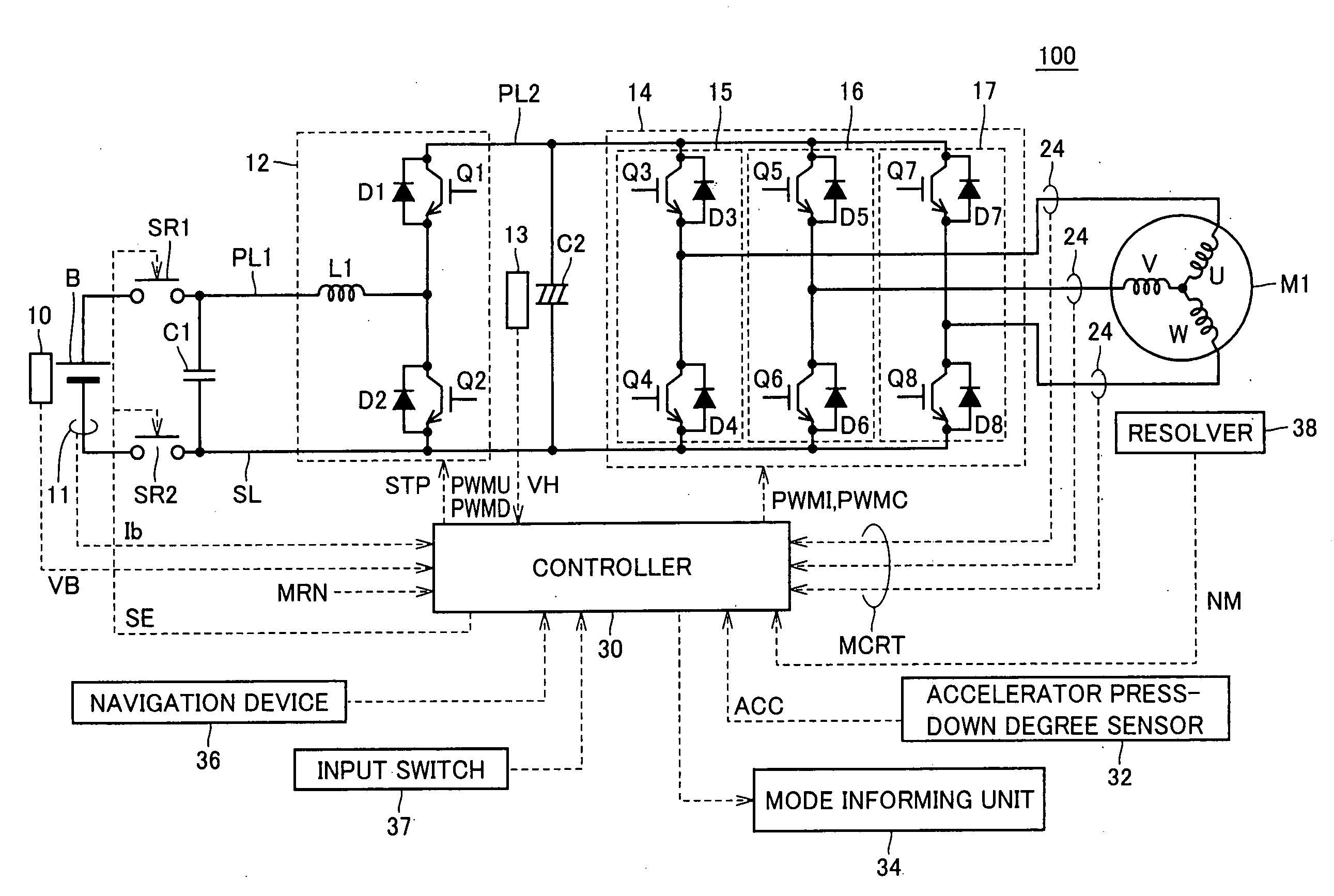
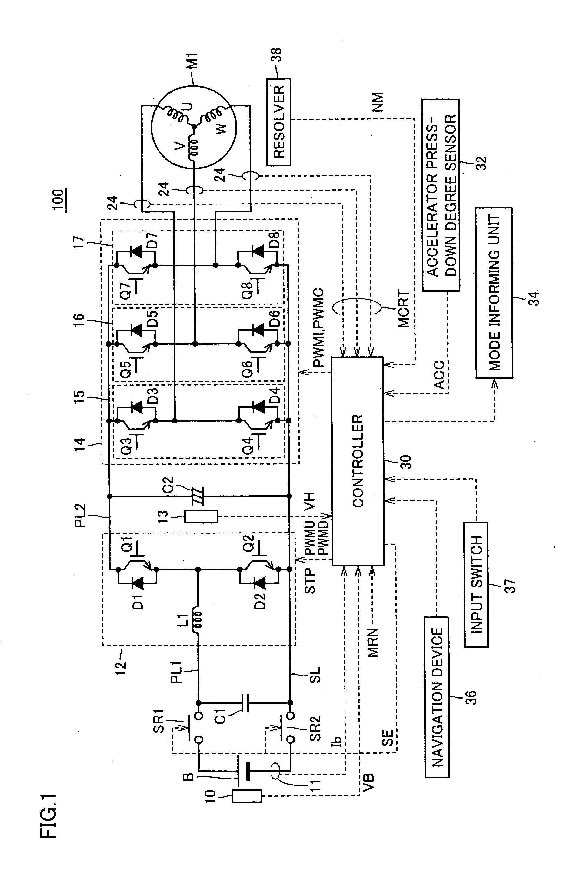
[0028]FIG. 1 is a circuit diagram of a motor drive device according to the embodiment of the invention.

[0029]With reference to FIG. 1, the motor drive device 100 includes a direct-current power supply B, voltage sensors 10, 13, system relays SR1, SR2, capacitors C1, C2, a boost converter 12, an inverter 14, current sensors 11, 24, and a controller 30.

[0030]An alternating-current motor M1 is a drive motor for generating torque for driving drive wheels of a hybrid car or an electric car. Alternatively, the motor may have a function as a motor driven by an engine and may be mounted in the hybrid car as a motor operating for the engine and capable of starting the engine, for example.

[0031]Boost converter 12 includes a reactor L1, NPN ...


PUM


Abstract

A motor drive device (100) includes a boost converter (12) boosting a power supply voltage and outputting a boosted voltage; an inverter (14) receiving the boosted voltage from the boost converter (12) and driving a motor (M1); and a controller (30) giving a target value of the boosted voltage to the boost converter (12) and setting one of a rectangular-wave control and a non-rectangular-wave control as a control method of the inverter (14). The controller (30) is capable of selecting from a first operation mode for giving a first boosted target value and designating the non-rectangular-wave control as the control method and a second operation mode for giving a second boosted target value lower than the first boosted target value and designating the rectangular-wave control as the control method, in response to a same predetermined input signal indicating a torque request.

Description

TECHNICAL FIELD[0001]The present invention relates to a motor controller, and particularly to a motor controller for a vehicle.BACKGROUND ART[0002]In recent years, as an environmentally friendly car, a vehicle using an electric motor, such as an electric car, a hybrid car, and a fuel-cell vehicle, is receiving broad attention.[0003]In such a hybrid car, an electric car, and the like, considerations are made on boosting a direct-current voltage from a power supply with a boost converter and converting the boosted direct-current voltage into an alternating voltage to drive a motor.[0004]Japanese Patent Laying-Open No. 2005-45880 describes switching of a control method of an inverter among a sinusoidal wave pulse-width-modulation (PWM) control, an overmodulation PWM control, and a rectangular-wave control in a hybrid car having such a boost converter.[0005]The rectangular-wave control involves a smaller switching loss and has higher system efficiency than the sinusoidal wave PWM contro...

Claims


Application Information

Patent Timeline
14 May 2009
Publication
US20090121669A1
IPC
H02P27/08; B60L9/18; H02P6/06; H02P6/08; H02P6/17; H02P6/28
CPC
B60L11/1807; B60L2210/14; Y02T10/7225; Y02T10/642; Y02T10/7005; H02P6/002; H02P6/28; B60L15/025
Inventors
HANADA, HIDETO