
Side scan sonar imaging system with boat position on display

a sonar imaging and position display technology, applied in the field of sonar imaging systems, can solve problems such as damage or loss of equipment, and achieve the effects of more area of coverage, faster and more complete imaging, and more accurate target locations

Active Publication Date: 2009-05-14
JOHNSON OUTDOORS
View PDF89 Cites 25 Cited by
  • Summary
  • Abstract
  • Description
  • Claims
  • Application Information

AI Technical Summary

Benefits of technology

The system provides improved maneuverability, reduced risk of equipment loss, enhanced imaging capabilities, and more accurate target location, enabling faster and more complete imaging of underwater environments without the limitations of traditional towed systems.

Problems solved by technology

Most natural and especially man-made lakes have rocks, stumps and standing timber that can snag a towfish and cause damage or loss of the equipment.

Method used


Image

  • Side scan sonar imaging system with boat position on display
  • Side scan sonar imaging system with boat position on display
  • Side scan sonar imaging system with boat position on display

Examples


Embodiment Construction

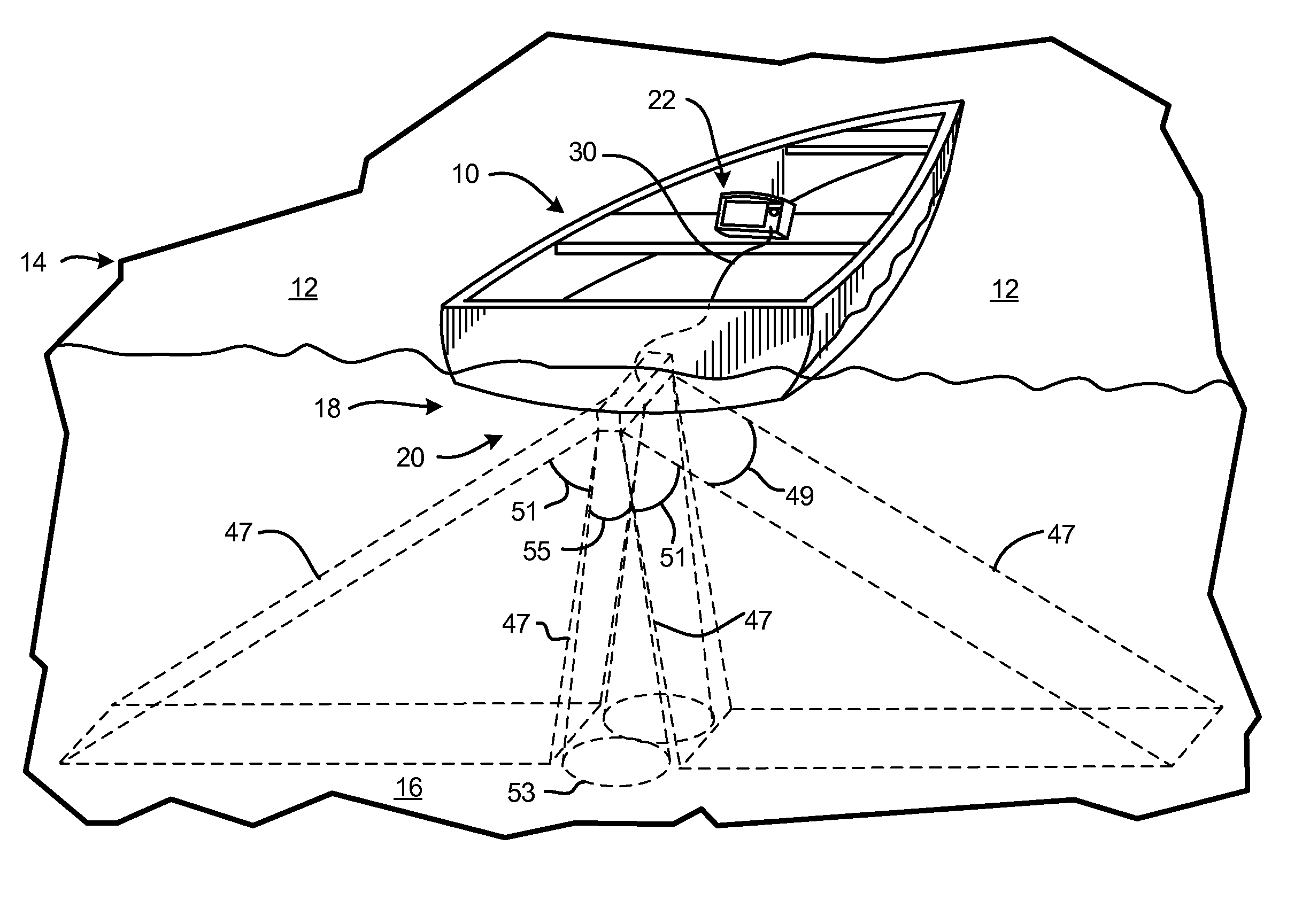
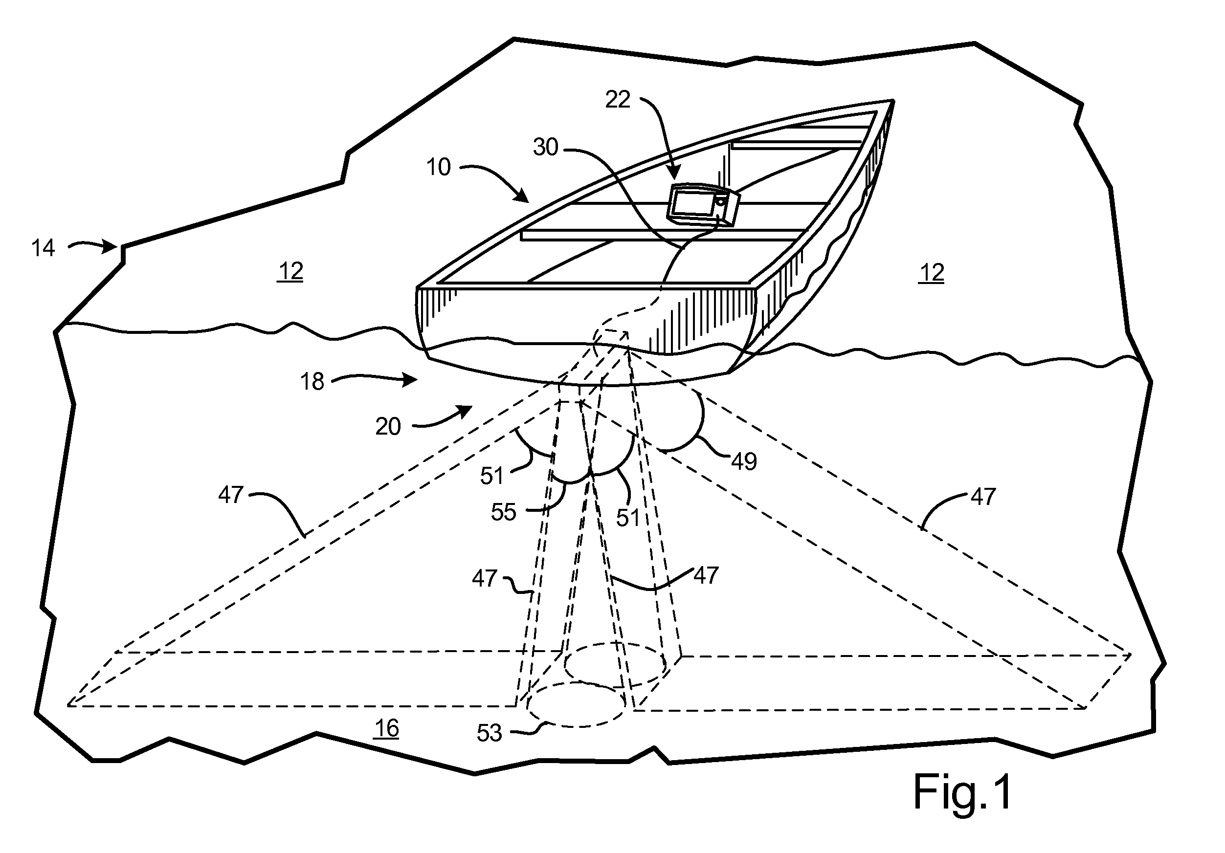
[0033]Turning now to the drawings, FIG. 1 illustrates a vessel (shown as a watercraft 10) on a surface 12 of a body of water 14 having a bottom 16. A sonar imaging system 18 is mounted or coupled to the watercraft 10 (e.g., rather than being towed by a flexible cable behind the watercraft 10) and is configured to scan the water below and to the sides of the watercraft (i.e., a boat mounted side scan sonar system). The sonar imaging system 18 comprises a transponder or transducer 20 coupled to an electronic control head unit 22 located at the watercraft 10. The sonar imaging system 18 repetitively scans the body of water 14 for fish and other underwater articles with transmissions of acoustic waves and receiving and displaying the sonar returns, with the duration of receiving being a function of the determined depth from a prior transmission.

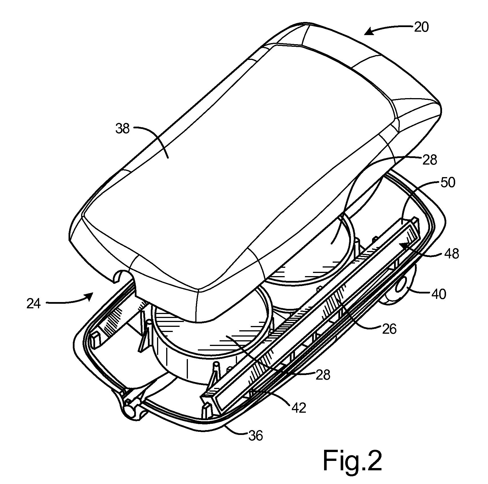
[0034]Referring to FIGS. 2-11, the transducer 20 includes a housing 24, a sonar array (in the form of a plurality of acoustic elements shown as ...


PUM


Abstract

A system for use with a boat to provide underwater sonar images includes a left side scan sonar transducer for transmitting left side scan sonar pulses and for receiving left side scan sonar return signals and a right side scan sonar transducer for transmitting right side scan sonar pulses and for receiving right side scan sonar return signals. The system further includes signal processing circuitry for processing the left and right side scan sonar return signals to produce side scan image data and a digital processor for providing signals to a display based upon the side scan image data to produce a display image on the display showing boat location, a water column between the boat and bottom, and an underwater image comprising at least one of a left side underwater image and a right side underwater image.

Description

CROSS-REFERENCE TO RELATED APPLICATION(S)[0001]This is a continuation of U.S. patent application Ser. No. 11 / 195,107, entitled “SONAR IMAGING SYSTEM FOR MOUNTING TO WATERCRAFT,” filed Aug. 2, 2005 by David A. Betts et al. and claims the benefit of U.S. Provisional Patent Application No. 60 / 598,326, filed Aug. 2, 2004, the teachings and disclosure of which are hereby incorporated in their entireties by reference thereto.[0002]Reference is also made to application Ser. No. ______ entitled “SIDE SCAN SONAR IMAGING SYSTEM WITH ASSOCIATED GPS DATA” and application Ser. No. ______entitled “SIDE SCAN SONAR IMAGING SYSTEM WITH IMAGE ENHANCEMENT”, which are filed on even date and are assigned to the same assignee as this application.FIELD OF THE INVENTION[0003]The present invention relates generally to sonar imaging systems for use in sport fishing applications such as in a fish finder, sonar depth sounder, etc., and more particularly to side scan sonar imaging systems for imaging of the und...

Claims


Application Information

Patent Timeline
Patent Type & Authority Applications(United States)
IPC IPC(8): G01S15/89G01S19/19
CPCG01S7/521G01S15/96G01S15/8902G01S15/107
Inventor BETTS, DAVID A.DERROW, ROBERT W.HOWELLS, DAVID J.
Owner JOHNSON OUTDOORS
Learn More