Supercharge Your Innovation With Domain-Expert AI Agents!

Mechanism for controlling position of optical element

a technology of optical elements and actuators, which is applied in the direction of mountings, instruments, camera body details, etc., can solve the problems of increasing the length of the spring run counter to space saving, power consumption, and the production cost of the drive source, etc., and achieves low power consumption and high level

Active Publication Date: 2009-05-14
HOYA CORP
View PDF2 Cites 11 Cited by
  • Summary
  • Abstract
  • Description
  • Claims
  • Application Information

AI Technical Summary

Benefits of technology

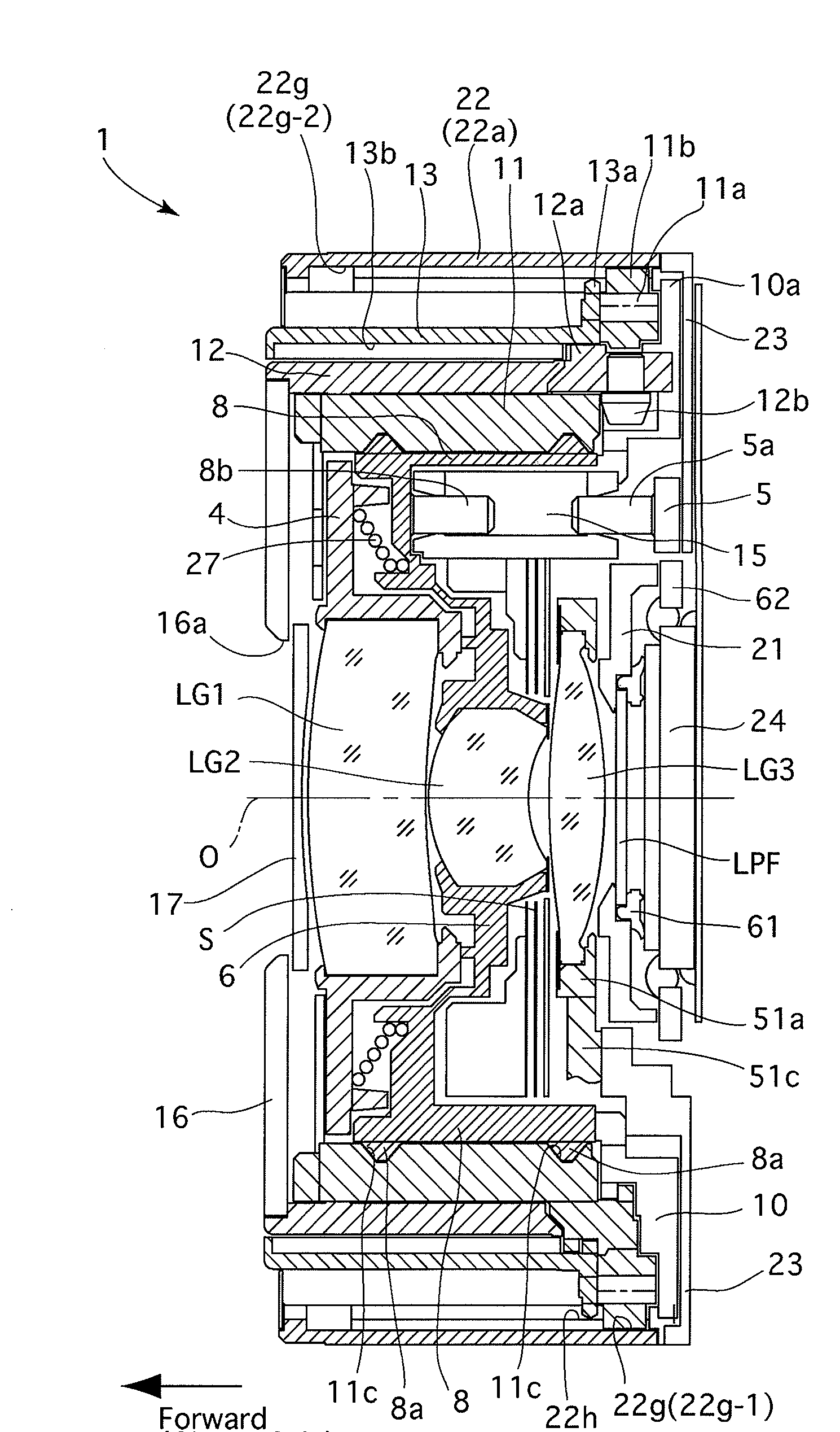
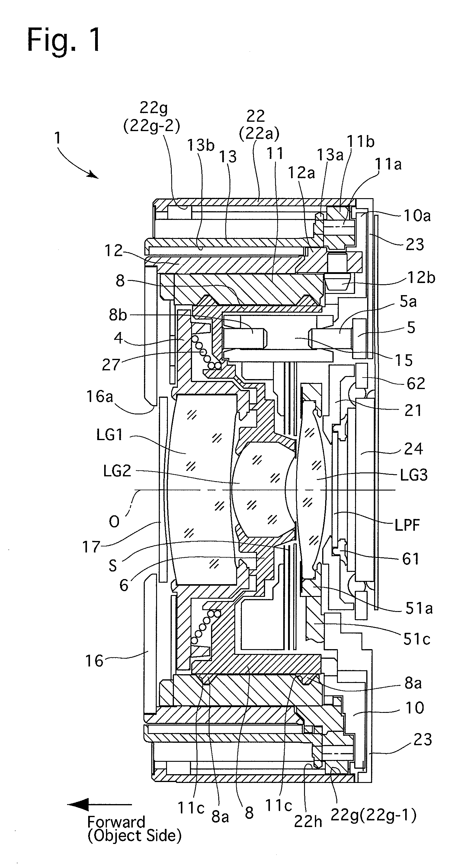
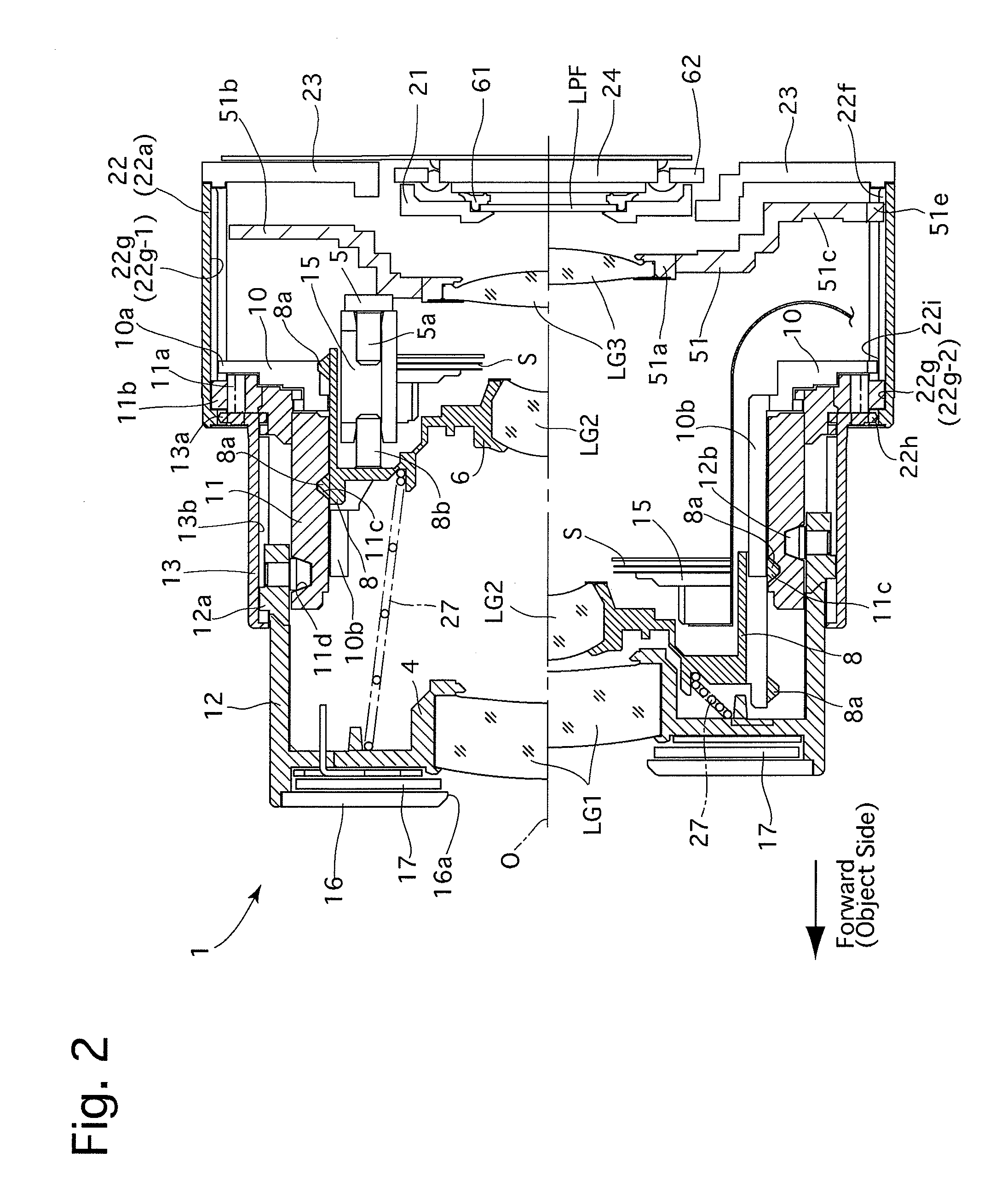
The present invention provides an optical element position control mechanism with reduced load variation of the biasing device caused by movement of the optical element holding member, and with low power consumption and space utilization. The mechanism includes a biasing device with a torsion spring that varies its resilient deformation in response to movement of the optical element holding member. The biasing device is securely protected from damage by external or internal contact with other elements or assembly workers. The mechanism also includes a drive mechanism and a rotational ring for moving the optical element holding member. The load variation of the biasing device is reduced by positioning the swing axis and the free end portion of the arm in separate spaces. The mechanism can be positioned without restrictions of a movable member, such as a rotational ring. The drive mechanism includes a screw shaft and a nut that move forward and rearward in the optical axis direction by rotating the screw shaft. A guide member with a guide surface inclined with respect to the optical axis direction and a follower that slides on the guide surface are used to determine the position of the optical element holding member.

Problems solved by technology

Namely, the greater the maximum load of the spring member, the stronger the drive source for the optical element holding member is required, which is disadvantageous with regard to the power consumption, the production cost and miniaturization of the apparatus containing the drive source.
However, in the conventional installation structure of the extension or compression spring for an optical element holding member, the spring load, which is varied according to the amount of spring extension, tends to have a large variation range, and accordingly, it is difficult to minimize the maximum spring load.
However, in optical devices produced in recent years which are in strong demand to be miniaturized, increasing the length of the spring runs counter to space saving and thus cannot be easily adopted.
Therefore, the length of the optical element holding member in the moving direction thereof is subjected to constraints of the length of the retracted lens barrel, so that it has been difficult to adopt a long spring as the biasing device for biasing the optical element holding member.
As a result, the aforementioned problem of the spring load having a large variation range easily occurs.
Additionally, although the variation range of the spring load can be reduced by reducing the amount of movement of the optical element holding member, the amount of movement of the optical element holding member (namely, the amount of movement of the optical element held by the optical element holding member) is originally determined to satisfy a required optical performance, and this optical performance may not be obtained if the amount of movement of the optical element holding member is limited.

Method used


Image

  • Mechanism for controlling position of optical element
  • Mechanism for controlling position of optical element
  • Mechanism for controlling position of optical element

Examples


third embodiment

[0099]In the third embodiment shown in FIGS. 18 through 20, the biasing device for biasing the third lens group frame 51 is composed of a combination of swing lever (arm / lever) 70 and a torsion spring (lever biasing member) 238. The housing 22 is provided with a swing support projection (swing movement support portion / swing center portion) 22m which projects laterally from the housing 22 (so that the axis of the swing support projection 22m extends in a direction substantially orthogonal to the vertical plane P1), and the swing lever 70 is provided at one end thereof with a shaft hole 70a into which the swing support projection 22m is inserted so that the swing lever 70 is freely rotatable about the swing support projection 22m and swingable about a swing axis 70x (fulcrum) which is substantially orthogonal to the optical axis O and substantially coincident with the axis of the swing support projection 22m. The other end (free end) of the swing lever 70 engages with a lever engagin...

first embodiment

[0107]For instance, in the optical element holding mechanism, by lengthening the biasing arm portion 38c with the torsion spring 38 being positioned outside the cylindrical portion 22a of the housing 22, the effect of reducing the load variation of the biasing device can be obtained even though the torsion spring 38 is not protected by the housing 22 as shown in FIG. 6. As shown in FIG. 24, the set of three cam ring control grooves 22g are formed on an inner peripheral surface of the cylindrical portion 22a of the housing 22 almost over the entire circumferential range thereof. Due to this structure, the cylindrical portion 22a needs to be a completely cylindrical body with no portions thereof missing in a circumferential direction. Although the housing 22 is made as a molded product of synthetic resin, it is difficult during manufacturing to mold the housing 22 into a housing having a double-walled structure in which the housing further includes a wall portion which is positioned r...


PUM


Abstract

An optical element position control mechanism includes an optical element holding member which holds an optical element of a photographing system and is guided in an optical axis direction; a drive mechanism for moving the optical element holding member in the optical axis direction; and a biasing device including an arm which is swingable about a swing axis, the swing axis being substantially orthogonal to the optical axis, and the arm extending substantially orthogonal to the swing axis and having a free end portion which engages with the optical element holding member to bias the optical element holding member in the optical axis direction.

Description

BACKGROUND OF THE INVENTION[0001]1. Field of the Invention[0002]The present invention relates to a mechanism for controlling the position of an optical element in an optical apparatus, more specifically to a structure which provides an optical element holding member, movable in an optical axis direction, with a biasing force in the moving direction of the optical element holding member.[0003]2. Description of the Related Art[0004]In optical apparatuses such as cameras, it is often the case that a biasing force in an optical axis direction is imparted to an optical element holding member which holds an optical element and can move in the optical axis direction for the purpose of providing the optical element holding member with a role in functioning as a part of the drive mechanism for driving the optical element holding member, eliminating backlash in the drive mechanism or stabilizing the position of the optical element holding member. The biasing device for biasing the optical ele...

Claims


Application Information

Patent Timeline
Patent Type & Authority Applications(United States)
IPC IPC(8): G03B17/00G02B7/02
CPCG02B7/102G02B7/10G03B13/36G03B13/00
Inventor NOMURA, HIROSHI
Owner HOYA CORP
Features
  • R&D
  • Intellectual Property
  • Life Sciences
  • Materials
  • Tech Scout
  • Unparalleled Data Quality
  • Higher Quality Content
  • 60% Fewer Hallucinations
Learn More