
CMP Pad Dressers

a pad and dresser technology, applied in the field of chemical engineering, metallurgy, materials science, can solve the problem of predetermined cutting configuration of abrasive tools

Active Publication Date: 2009-05-14
KINIK
View PDF105 Cites 27 Cited by
  • Summary
  • Abstract
  • Description
  • Claims
  • Application Information

AI Technical Summary

Benefits of technology

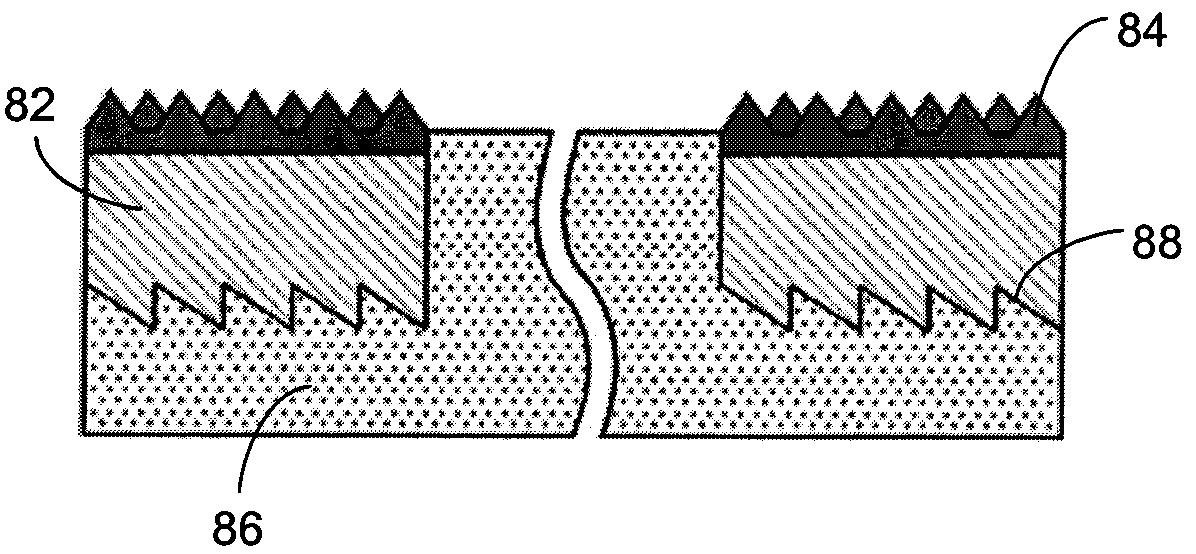
[0016]In accordance with another aspect of the invention, a method of conditioning a CMP pad is provided, including: engaging material of the CMP pad with a cutting tip of at least one cutting element; moving the cutting element and the CMP pad relative to one another to thereby remove material from the CMP pad with the cutting tip of the cutting element to create an exposed layer of CMP pad material; engaging the exposed layer of CMP pad material with the cutting tip of the cutting element, or with a cutting tip of a second cutting element; and moving the cutting element engaged with the exposed layer of CMP pad material and the CMP pad relative to one another to thereby remove the exposed layer of CMP pad material.

Problems solved by technology

The selection, arrangement, and setting of the tool precursors can result in an abrasive tool having a predetermined cutting configuration.

Method used


Image

  • CMP Pad Dressers
  • CMP Pad Dressers
  • CMP Pad Dressers

Examples


Embodiment Construction

[0048]Before the present invention is disclosed and described, it is to be understood that this invention is not limited to the particular structures, process steps, or materials disclosed herein, but is extended to equivalents thereof as would be recognized by those ordinarily skilled in the relevant arts. It should also be understood that terminology employed herein is used for the purpose of describing particular embodiments only and is not intended to be limiting.

[0049]It must be noted that, as used in this specification and the appended claims, the singular forms “a,”“an” and, “the” include plural referents unless the context clearly dictates otherwise. Thus, for example, reference to “a CMP pad dresser” includes one or more of such dressers, reference to “an operating parameter” includes reference to one or more of such operating parameters, and reference to “the asperity” includes reference to one or more of such asperities.

[0050]Definitions

[0051]In describing and claiming th...


PUM


Abstract

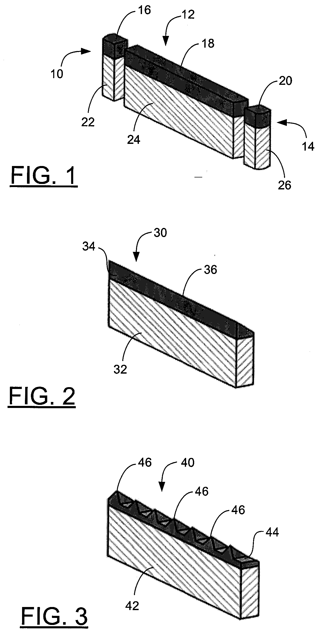
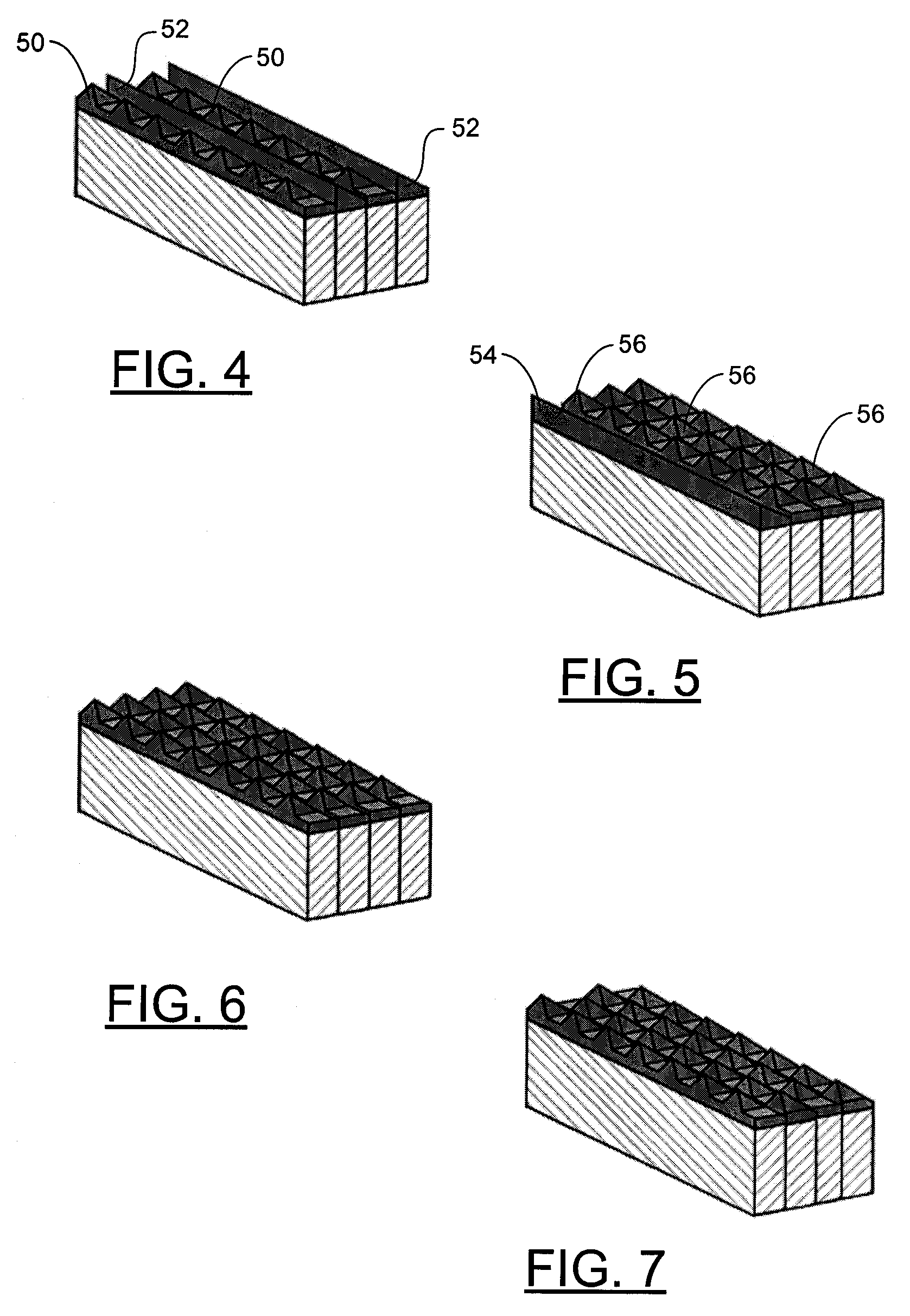
An abrasive tool includes an assembly of tool precursors. At least one of the tool precursors has a continuous polycrystalline diamond, polycrystalline cubic boron nitride, or ceramic material cutting element formed into a blade shape. The abrasive tool can additionally include a setting material, which is configured to attach the tool precursors and form a single mass. The selection, arrangement, and setting of the tool precursors can result in an abrasive tool having a predetermined cutting configuration. Methods for forming such an abrasive tool are also disclosed.

Description

PRIORITY CLAIM[0001]This application claims the benefit of: U.S. Provisional Patent Application Ser. No. 60 / 987,687, filed Nov. 13, 2007; and U.S. Provisional Patent Application Ser. No. 60 / 988,643, filed Nov. 16, 2007, each of which is hereby incorporated herein by reference.FIELD OF THE INVENTION[0002]The present invention relates generally to devices and methods for use in connection with dressing or conditioning a chemical mechanical polishing (CMP) pad. Accordingly, the present invention involves the fields of chemical engineering, chemistry, metallurgy, and materials science.BACKGROUND OF THE INVENTION[0003]Chemical mechanical process (CMP) has become a widely used technique for polishing certain work pieces. Particularly, the computer manufacturing industry has begun to rely heavily on CMP processes for polishing wafers of ceramics, silicon, glass, quartz, metals, and mixtures thereof for use in semiconductor fabrication. Such polishing processes generally entail applying the...

Claims


Application Information

Patent Timeline
IPC IPC(8): B24D3/00
CPCB24B53/017Y10T428/2457Y10T428/24612
Inventor SUNG, CHIEN-MIN
Owner KINIK
Learn More