Ultra-rapid freezing device and method

Active Publication Date: 2009-05-21
MAX PLANCK GESELLSCHAFT ZUR FOERDERUNG DER WISSENSCHAFTEN EV
View PDF3 Cites 36 Cited by
  • Summary
  • Abstract
  • Description
  • Claims
  • Application Information

AI Technical Summary

Benefits of technology

[0047]Similarly, much thinner channels (a few tens of nanometer thin fluid layer and top/bottom walls) could serve to confine highly concentrated solutions of pure proteins in a thin layer, which would yield a high-quality specimen for protein structure determination by electron cryo-microscopy. Specimen preparatio

Problems solved by technology

Microscopy with light, electrons, and nanomechanical probes has revolutionized biology, yet at room temperature, the potential of many techniques can not be fully exploited due to thermal noise, radiation damage, or mechanical interactions with the object.
Cryogenic imaging has advanced greatly in recent years, but the fixation of biological specimens for this purpose is a difficult challenge due to the need to prevent ice crystal formation upon cooling.
Subtle alterations of cell state due to these manipulations are inherently unavoidable, and have therefore always been tacitly accepted by the community.
However such rapid cooling currently is far beyond the limitations of conventional techniques; therefore, the requirement is usually relaxed by adding cryo-protectants, which may be toxic to the cell and can subtly alter physical structure and biochemical composition.
The attractiveness of

Method used


Image

  • Ultra-rapid freezing device and method
  • Ultra-rapid freezing device and method
  • Ultra-rapid freezing device and method

Examples


first embodiment

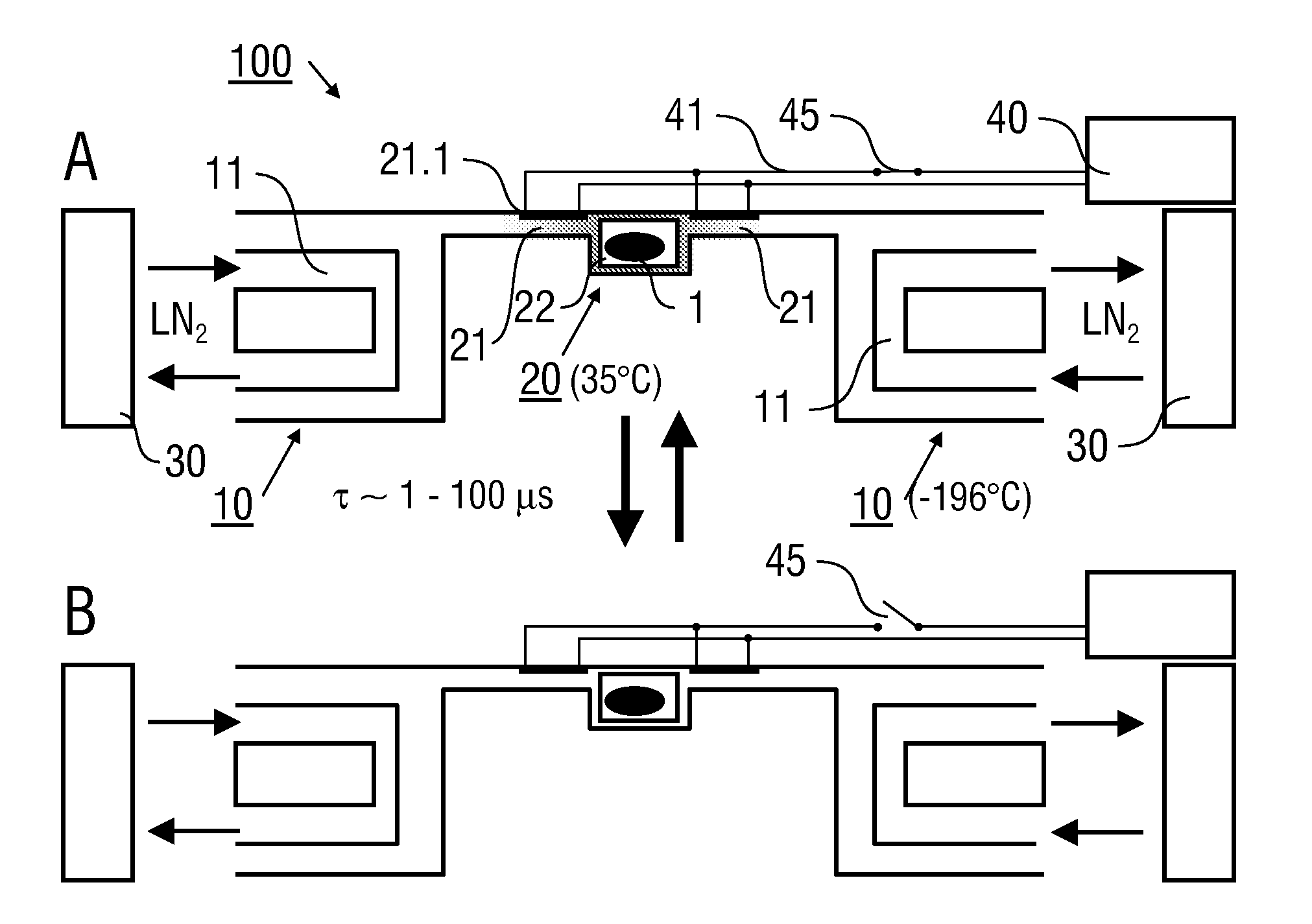
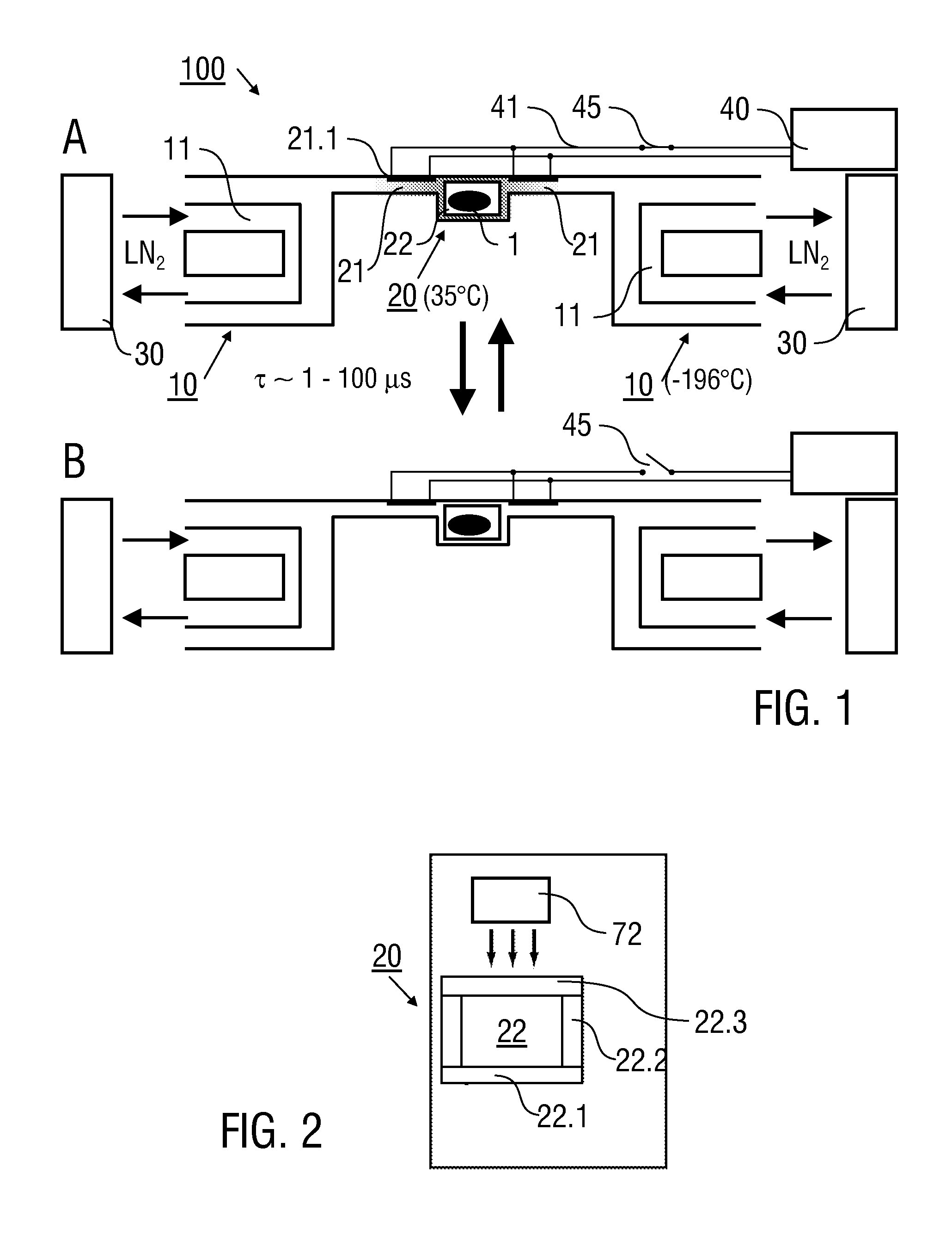
[0061]FIG. 1 illustrates an ultra-rapid freezing device 100 according to the invention in a heated state (FIG. 1A) and in a cooled state (FIG. 1B). The ultra-rapid freezing device 100 comprises the substrate chip 10 (partially shown) and the sample carrier 20. The cross-sectional view of FIG. 1 shows that the sample carrier 20 comprises a thin microfluidic channel 22 which is attached to the substrate chip 10 through heated support beams 21. The substrate chip 10 includes a cold reservoir formed by cooling medium channels 11. The cooling medium channels 11 are formed in the chip body on opposite sides of the sample carrier. The cooling medium channels 11 are connected with a coolant supply source 30 (schematically illustrated). The coolant supply source 30 comprises a reservoir of liquid nitrogen being connected via conduction lines and control valves (not shown) with the cooling medium channels 11.

[0062]The channel 22 of the sample carrier 20 (see also FIG. 2) has a rectangular cro...

third embodiment

[0088]FIG. 10A illustrates a schematic top view of the ultra-rapid freezing device 100 adapted for imaging of rapid transients of chemical or biochemical reactions. The ultra-rapid freezing device 100 comprises a plurality of sample carriers 20 each of which being connected with the substrate chip 10. The sample carriers 20 comprise a plurality of parallel channels 22 with inlets 22.4 and outlets 22.5. The sample carriers 20 are adapted for an electroporation of biological cells. To this end, electroporation electrodes 22.6 are integrated into the channels 22 as illustrated in the lower partial image of FIG. 10B.

[0089]Uptake and transport of fluorescent molecules after electroporation can be investigated by simultaneous imaging a plurality of cells 1, 2, 3, . . . suspended in a solution including fluorescent molecules. The cells 1, 2, 3 . . . are simultaneously subjected to a high voltage electroporation pulse at time t0. Subsequently, the cells 1, 2, 3, . . . are frozen with specif...


PUM


Abstract

An ultra-rapid freezing device (100) adapted for cooling a sample (1), includes a substrate chip (10) being adapted for cooling the sample (1), and at least one sample carrier (20) being adapted for accommodating the sample (1) and including at least one heatable support (21), through which the at least one sample carrier (20) is attached to the substrate chip (10). Preferably, the at least one sample carrier (20) is attached to the substrate chip (10) in a suspended manner. Furthermore, a method of ultra-rapid freezing a sample (1) is described. The at least one sample carrier (20) can be switched between a heated state at which a thermal gradient is formed relative to the substrate chip (10) and a cooled state at which a thermal equilibrium is formed relative to the substrate chip (10).

Description

CROSS-REFERENCE TO RELATED APPLICATIONS[0001]This specification claims priority of the provisional U.S. patent application Ser. No. 60 / 989,165 filed on Nov. 20, 2007.STATEMENT REGARDING FEDERALLY SPONSORED RESEARCH[0002]This invention was made with U.S. government support under Grant #DAAD 19-03-D-0004 awarded by the Army Research Office. The U.S. government has certain rights in this invention.SUBJECT OF THE INVENTION[0003]The present invention relates to an ultra-rapid freezing device (flash-freezing device) for cooling a sample, in particular to an ultra-rapid freezing device being adapted for an ultra-rapid freezing of a biological sample. Furthermore, the present invention relates to a method for ultra-rapidly freezing (flash-freezing) a sample, in particular for an ultra-rapid freezing of biological samples. The invention can be applied for ultra-rapid freezing of synthetic or biological samples, in particular for investigations of biological samples, like in e.g. cryogenic im...

Claims


Application Information

Patent Timeline
IPC IPC(8): F25B19/00H05B3/02F26B19/00C12Q1/70C12N5/06C12Q1/02
CPCA01N1/02G01N1/42F25D3/10A01N1/0252
Inventor BURG, THOMAS P.
Owner MAX PLANCK GESELLSCHAFT ZUR FOERDERUNG DER WISSENSCHAFTEN EV
Why Eureka
Try Eureka