

Internal combustion engine electric discharge structure
a technology of electric discharge and internal combustion engine, which is applied in the direction of machines/engines, spark plugs, sparking plugs, etc., can solve the problems of achieve the effects of improving the autoignition properties of air-fuel mixture, low efficiency of radical generation and limited amount of radicals
- Summary
- Abstract
- Description
- Claims
- Application Information
AI Technical Summary
Benefits of technology
Problems solved by technology
Method used
Image

Examples
second embodiment
[0139]Referring now to FIG. 18, an internal combustion engine electric discharge structure in accordance with a second embodiment will now be explained. Basically, in this second embodiment, the internal combustion engine electric discharge structure of the first embodiment is replaced in FIG. 1 with a modified structure as discussed below. In view of the similarity between the first and second embodiments, the parts of the second embodiment that are identical to the parts of the first embodiment will be given the same reference numerals as the parts of the first embodiment. Moreover, the descriptions of the parts of the second embodiment that are identical to the parts of the first embodiment can be omitted for the sake of brevity.
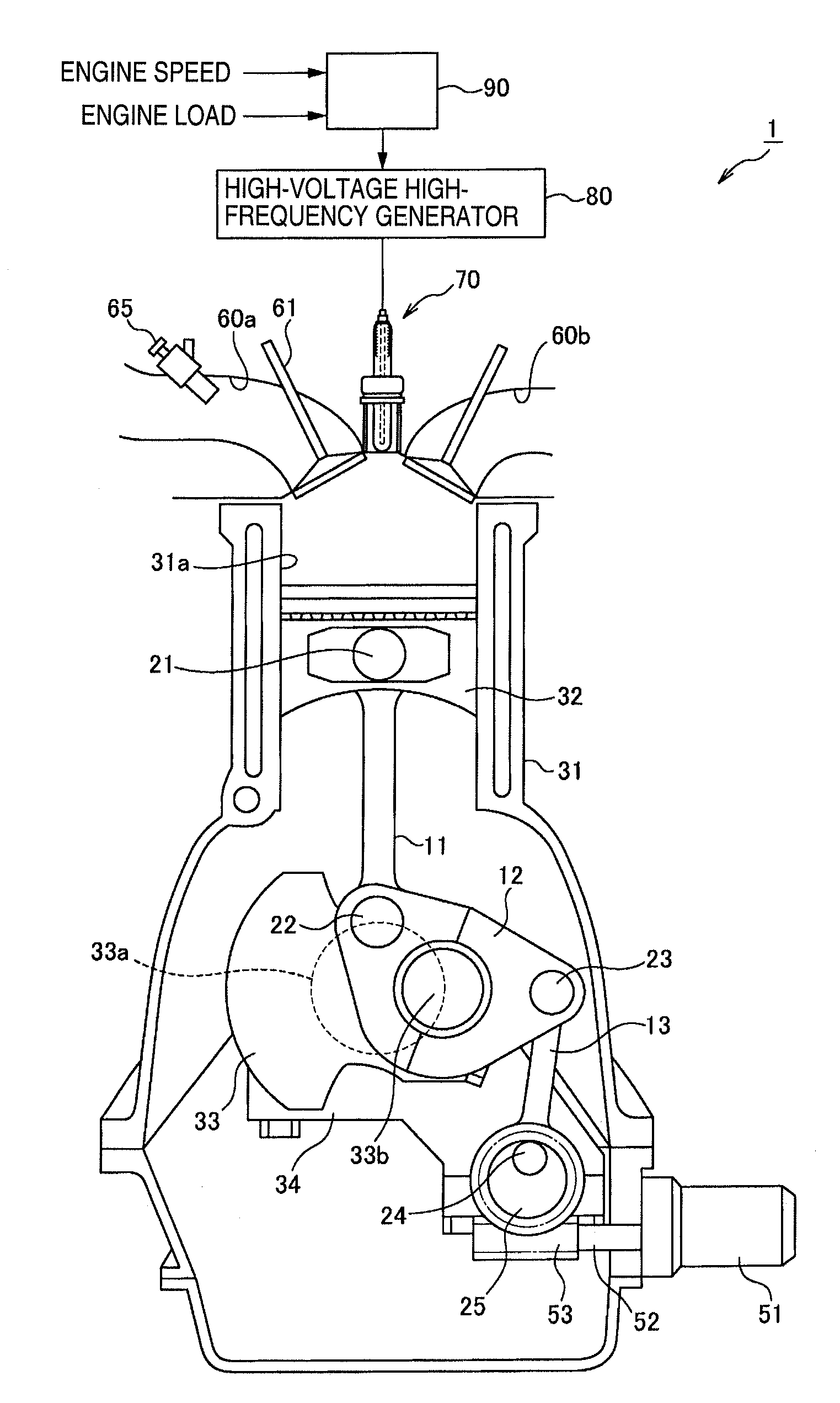
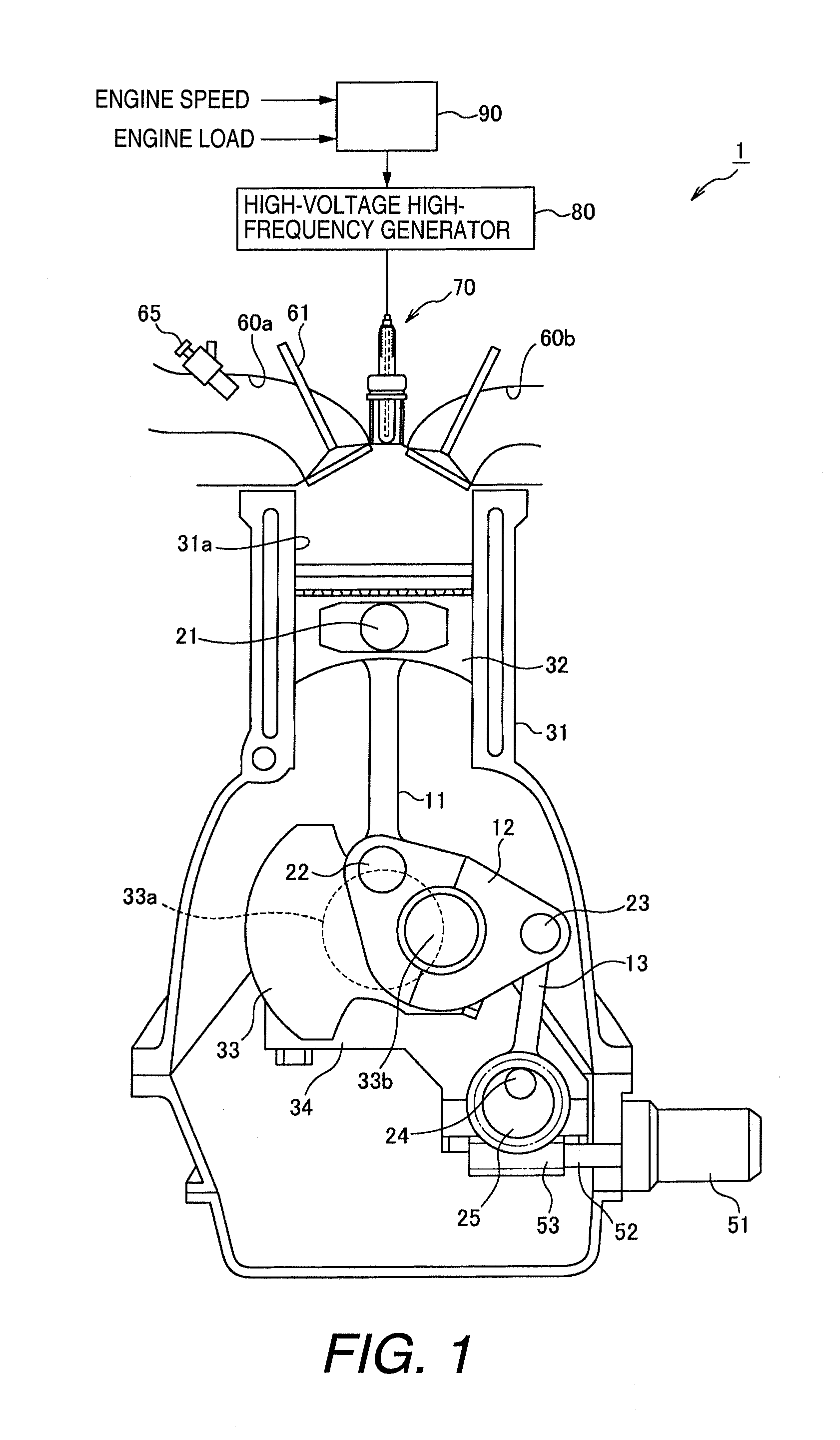
[0140]FIG. 18 is a simplified schematic cross-sectional view showing the operational configuration of the engine having an electric discharge structure in accordance with a second embodiment. The engine 1 having a barrier discharge function of the first e...
third embodiment
[0145]Referring now to FIG. 21, an internal combustion engine electric discharge structure in accordance with a third embodiment will now be explained. Basically, in this third embodiment, the internal combustion engine electric discharge structure of the first embodiment is replaced in FIG. 1 with a modified structure as discussed below. In view of the similarity between the first and second embodiments, the parts of the third embodiment that are identical to the parts of the first embodiment will be given the same reference numerals as the parts of the first embodiment. Moreover, the descriptions of the parts of the third embodiment that are identical to the parts of the first embodiment can be omitted for the sake of brevity.
[0146]FIG. 21 is a simplified schematic cross-sectional view showing the third embodiment of an engine having a barrier discharge function. In the barrier discharge device 70 of the present embodiment, a dielectric layer (insulating layer) 73 is formed on the...
fourth embodiment
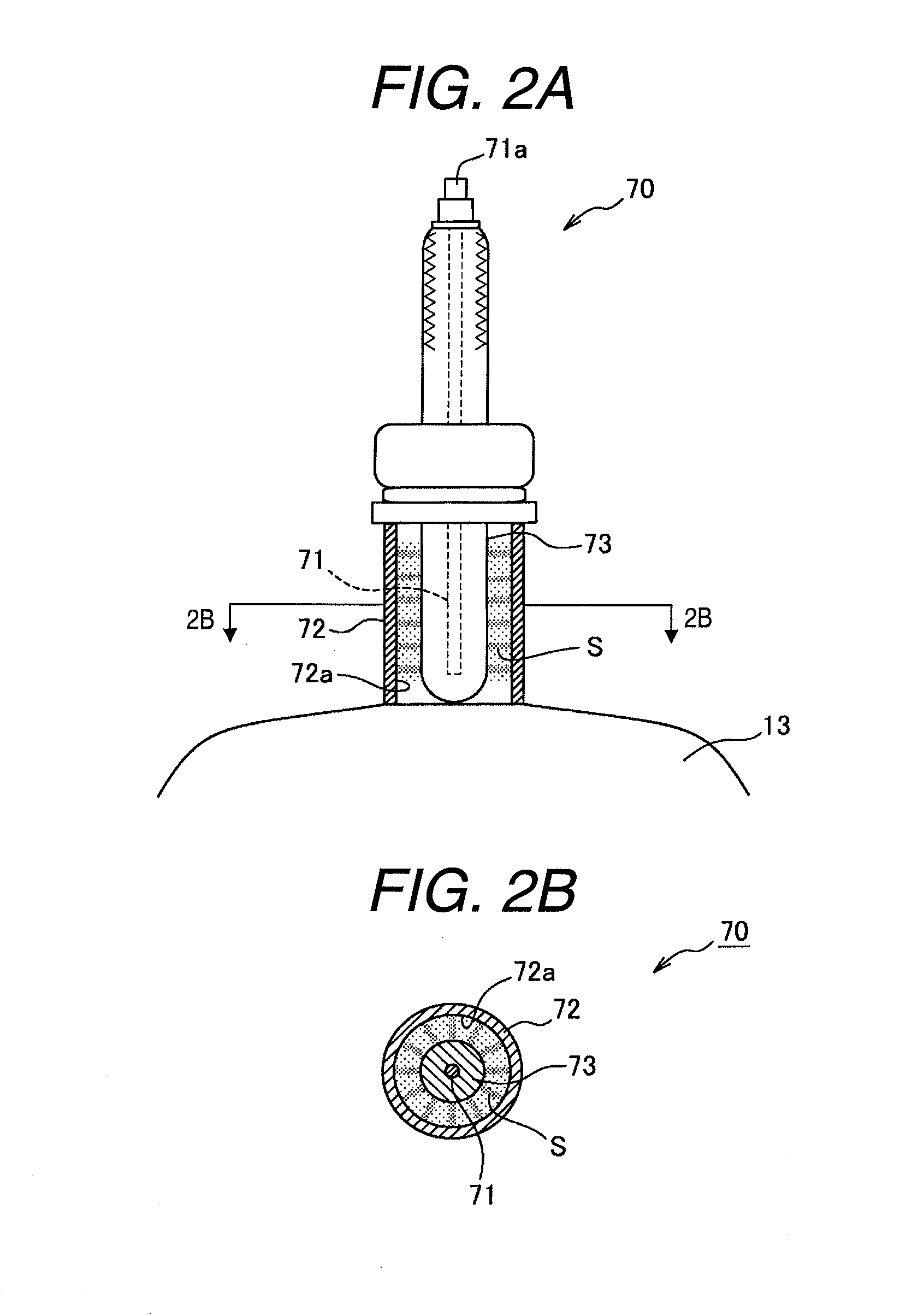
[0147]Referring now to FIGS. 22A and 22B, an internal combustion engine electric discharge structure in accordance with a fourth embodiment will now be explained. Basically, in this fourth embodiment, the internal combustion engine electric discharge structure of the first embodiment is replaced in FIG. 1 with a modified structure as discussed below. In view of the similarity between the first and fourth embodiments, the parts of the fourth embodiment that are identical to the parts of the first embodiment will be given the same reference numerals as the parts of the first embodiment. Moreover, the descriptions of the parts of the fourth embodiment that are identical to the parts of the first embodiment can be omitted for the sake of brevity.
[0148]FIGS. 22A and 22B contain simplified schematic cross-sectional views showing the fourth embodiment of the engine having a barrier discharge function. In the barrier discharge device 70 of the present embodiment, in contrast to the first em...
PUM
 Abstract
Description
Claims
Application Information