

Engine control apparatus and method
- Summary
- Abstract
- Description
- Claims
- Application Information
AI Technical Summary
Benefits of technology
Problems solved by technology
Method used
Image

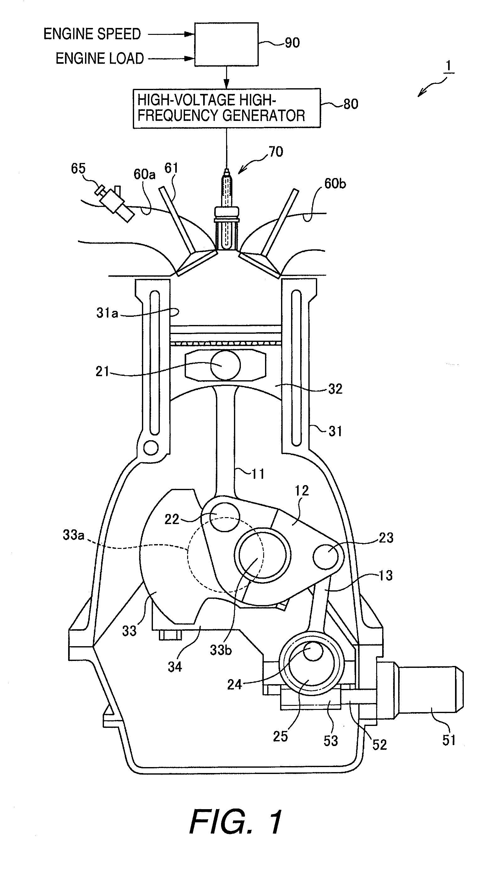
Examples
second embodiment
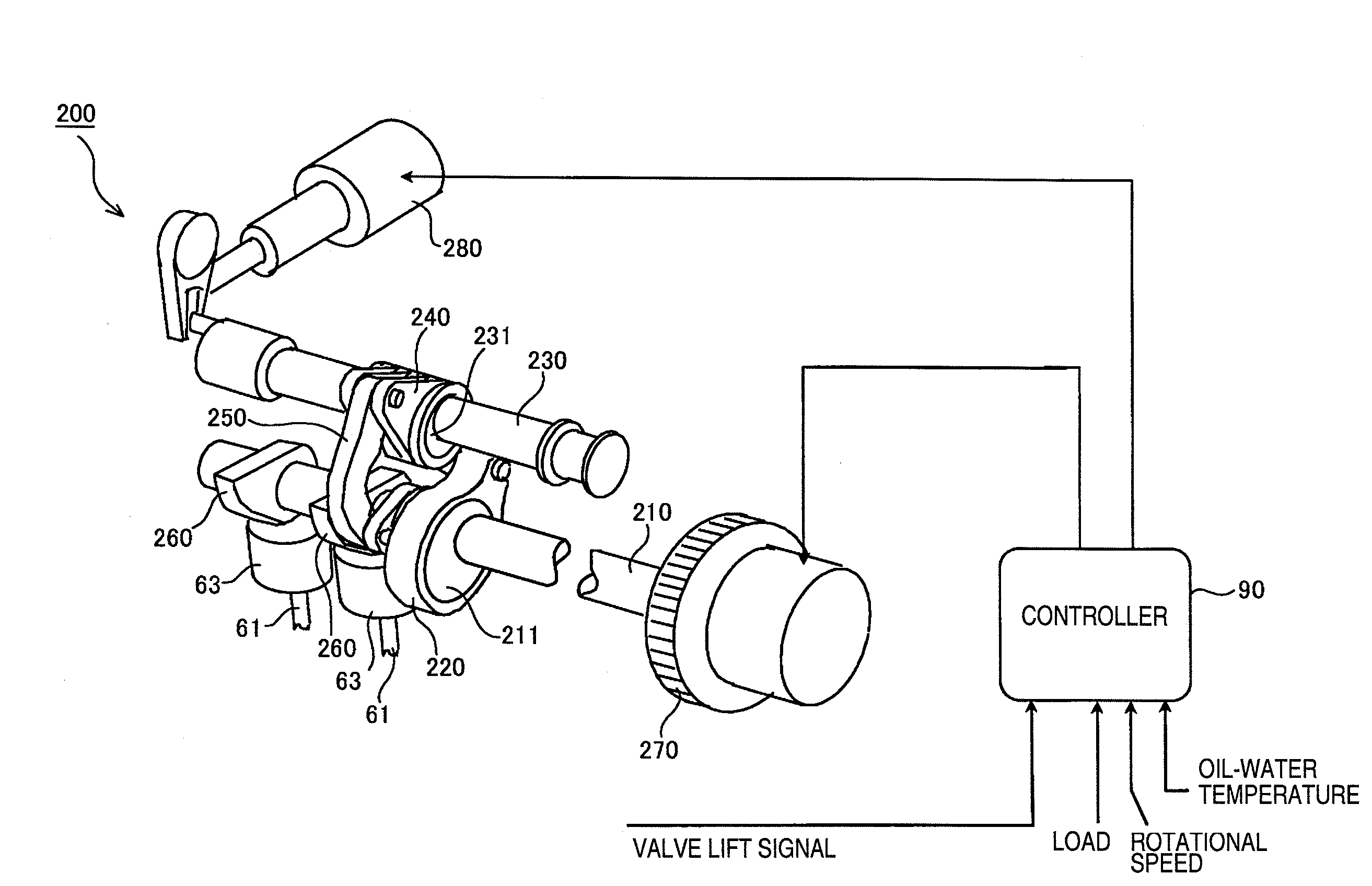
[0139]Referring now to FIG. 17, an engine control apparatus in accordance with a second embodiment will now be explained. Basically, in this second embodiment, the engine control apparatus of the first embodiment is replaced in FIG. 1 with a modified structure as discussed below. In view of the similarity between the first and second embodiments, the parts of the second embodiment that are identical to the parts of the first embodiment will be given the same reference numerals as the parts of the first embodiment. Moreover, the descriptions of the parts of the second embodiment that are identical to the parts of the first embodiment can be omitted for the sake of brevity.
[0140]FIG. 17 is a simplified schematic cross-sectional view showing the operational configuration of the engine control apparatus having an electric discharge device in accordance with a second embodiment. The engine 1 having a non-equilibrium plasma discharge function of the first embodiment was a so-called port-i...
third embodiment
[0145]Referring now to FIG. 20, an engine control apparatus in accordance with a third embodiment will now be explained. Basically, in this third embodiment, the engine control apparatus of the first embodiment is replaced in FIG. 1 with a modified structure as discussed below. In view of the similarity between the first and second embodiments, the parts of the third embodiment that are identical to the parts of the first embodiment will be given the same reference numerals as the parts of the first embodiment. Moreover, the descriptions of the parts of the third embodiment that are identical to the parts of the first embodiment can be omitted for the sake of brevity.
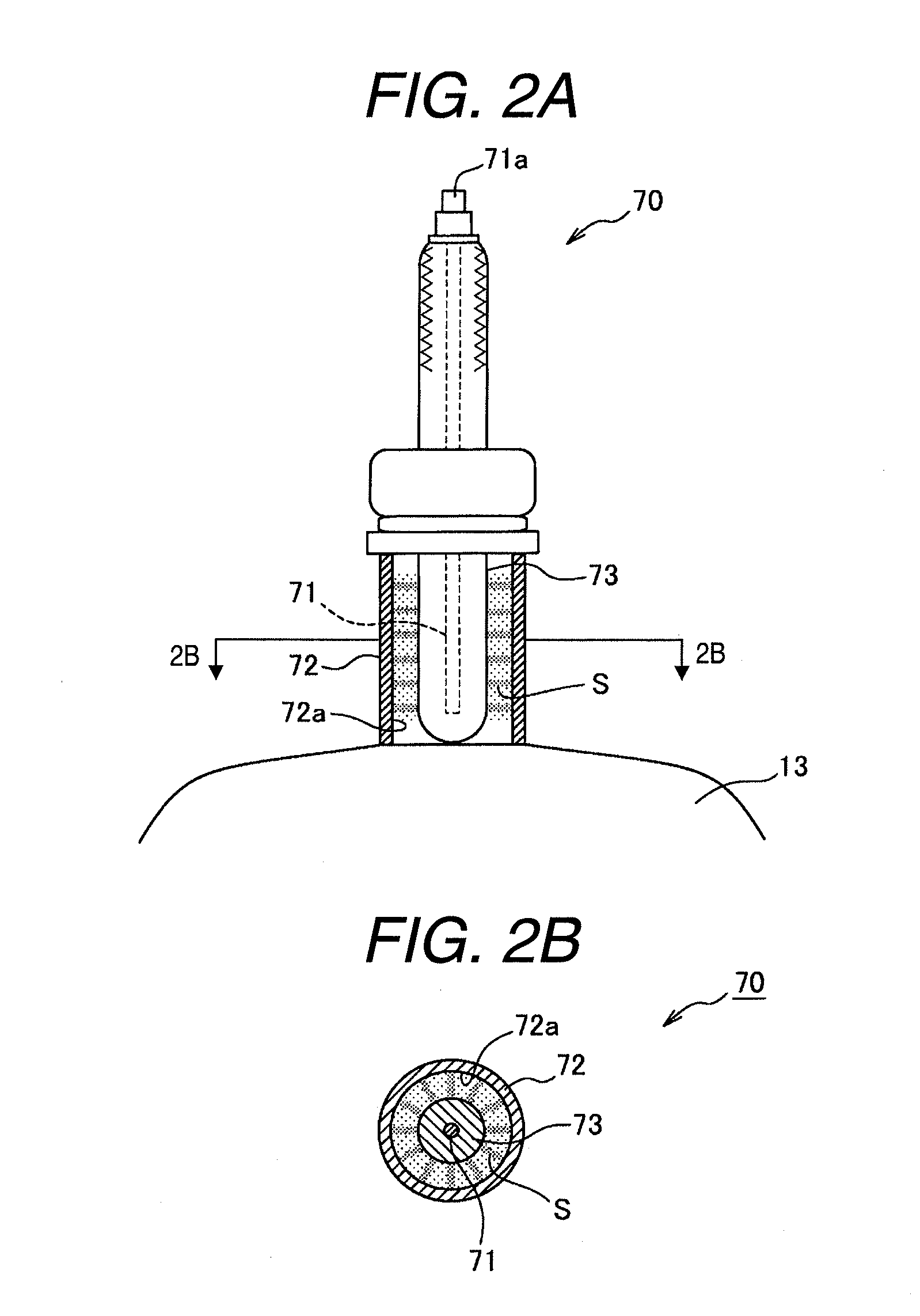
[0146]FIG. 20 is a simplified schematic cross-sectional view showing the third embodiment of the engine control apparatus having an electric discharge device. In the non-equilibrium plasma discharge device 70 of the present embodiment, a dielectric layer (insulating layer) 73 is formed on the inner periphery of the tubu...
fourth embodiment
[0147]Referring now to FIGS. 21A and 21B, an engine control apparatus in accordance with a fourth embodiment will now be explained. Basically, in this fourth embodiment, the engine control apparatus of the first embodiment is replaced in FIG. 1 with a modified structure as discussed below. In view of the similarity between the first and fourth embodiments, the parts of the fourth embodiment that are identical to the parts of the first embodiment will be given the same reference numerals as the parts of the first embodiment. Moreover, the descriptions of the parts of the fourth embodiment that are identical to the parts of the first embodiment can be omitted for the sake of brevity.
[0148]FIGS. 21A and 21B contain simplified schematic cross-sectional views showing the fourth embodiment of the engine control apparatus having an electric discharge device. In the non-equilibrium plasma discharge device 70 of the present embodiment, in contrast to the first embodiment, the central electro...
PUM
 Abstract
Description
Claims
Application Information