Electric charged particle beam microscope and microscopy

a technology of electric charge and beam microscope, applied in the field of electric charge particle beam microscope and microscopy, can solve the problems of insufficient accuracy, limited correction error, and long time consumption, and achieve the effects of reducing the need for the present technique, reducing the damage of specimens, and reducing the tat of image pickup

Inactive Publication Date: 2009-05-21
HITACHI HIGH-TECH CORP
View PDF14 Cites 34 Cited by
  • Summary
  • Abstract
  • Description
  • Claims
  • Application Information

AI Technical Summary

Benefits of technology

[0020]In the specimen rotation series image pickup, many images are picked up one by one and therefore a reduction in image pickup TAT is demanded eagerly and the need for the present technique is very high. In addition, this advantage can also lead to a reduction in sp

Problems solved by technology

In the technique disclosed in JP-A-2001-312989, the correction error is limited by an error in positioning the specimen stage.
The specimen stage positioning error is of μm order, leading to insufficient accuracy.
Skill is required for the adjustment and depending on operators, a very long time will sometimes be consumed.
The correction error in the case of using the technique of JP-A-8-106873 is also limited by the specimen stage positioning error and is of μm order, resulting in insufficient accuracy.
But the position correction time during the rotation series image

Method used


Image

  • Electric charged particle beam microscope and microscopy
  • Electric charged particle beam microscope and microscopy
  • Electric charged particle beam microscope and microscopy

Examples


embodiment 1

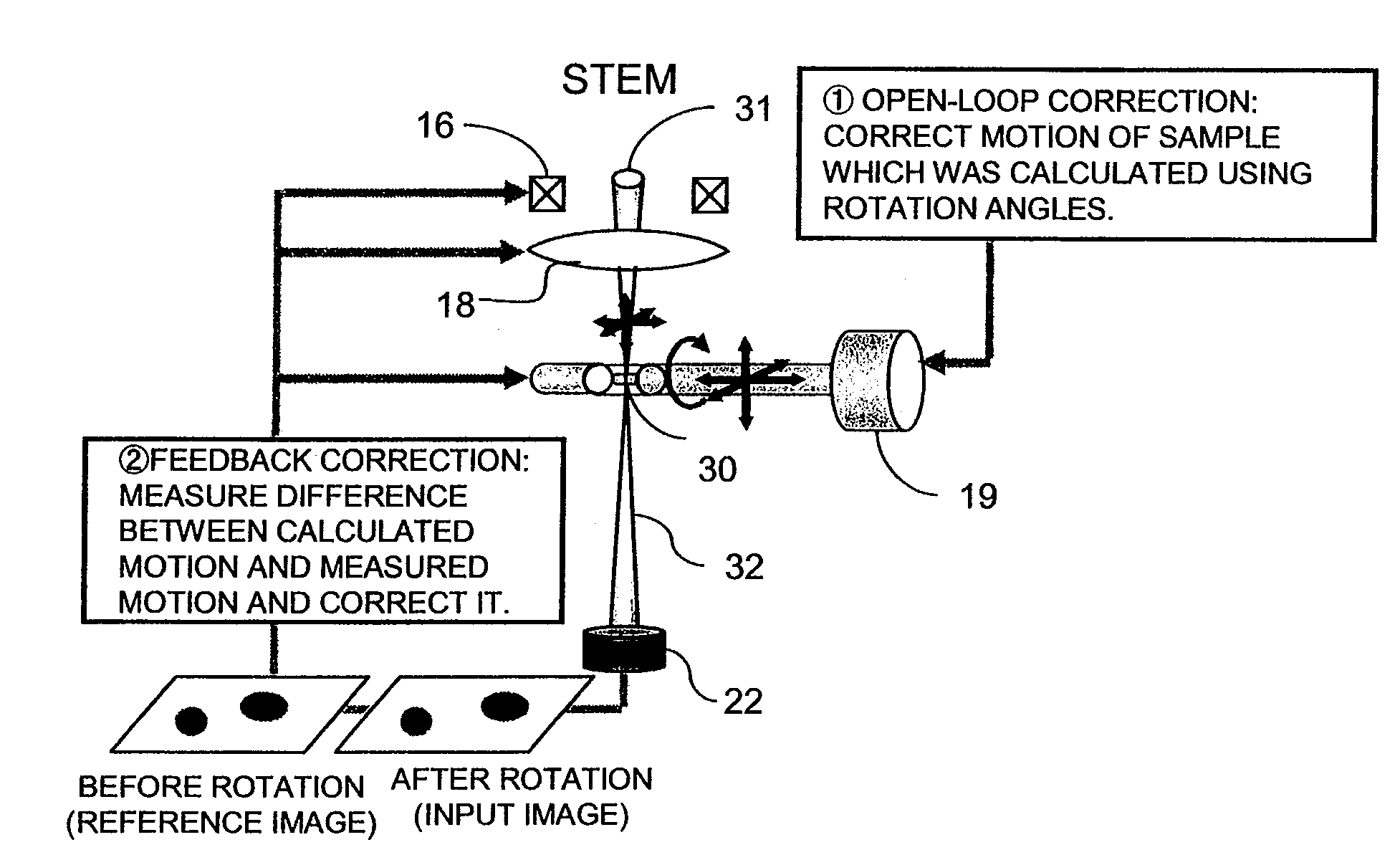
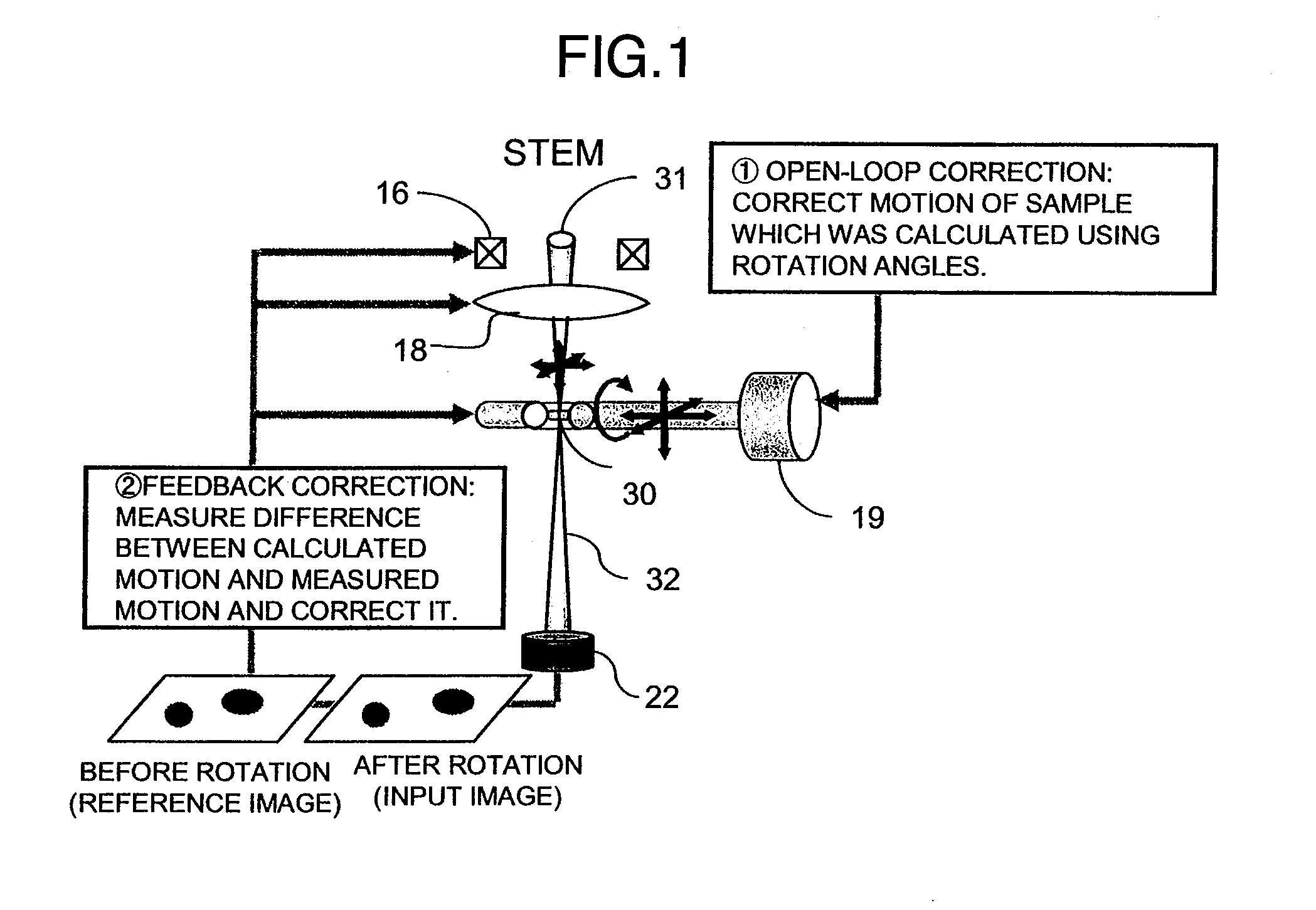
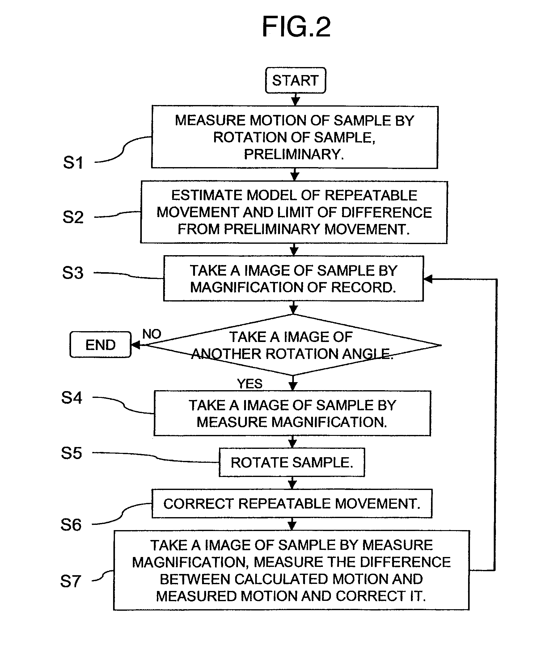
[0041]Referring now to FIG. 1, a system is illustrated schematically. The specimen movement due to the specimen rotation is sorted into a repeatable movement due to a shift between the specimen rotation axis and the specimen position and a non-repeatable movement due to mechanical position setting errors of a specimen rotation mechanism and a specimen moving mechanism and corrections appropriate to the respective types will be made. The repeatable movement is corrected through open-loop correction based on records. The non-repeatable movement is corrected through feedback correction in which a specimen movement is measured and corrected by using an image picked up each time the movement takes place. In the open-loop correction, a repeatable movement is modeled, XYZ movement amounts are calculated from a specimen rotation angle and then, control signals necessary to cancel out the XYZ movement amounts are transmitted to any one or more of specimen stage 19, deflection coil 16 and obj...

embodiment 2

[0077]The present embodiment is directed to an instance where the system for correcting the specimen movement due to the specimen rotation is applied to TEM observation of s specimen worked to a thin film. The fundamental construction of a TEM used in the present embodiment is illustrated in FIG. 17. The TEM comprises an electron gun 11 for emitting a primary electron beam 31, a control unit 11′ for controlling accelerating voltage and extraction voltage for the primary electron beam 31, a condenser lens 12 for adjusting the focus condition of the primary electron beam 31, a control unit 12′ for controlling the current value of the condenser lens 12, a condenser aperture 13 for controlling a divergent angle of primary electron beam 31, a control unit 13′ for controlling the position of the condenser aperture, an alignment deflector 14 for adjusting the incidence angle of the primary electron beam 31 incident on a specimen 30, a control unit 14′ for controlling the current value of t...


PUM


Abstract

An electric charged particle beam microscope is provided in which a specimen movement due to a specimen rotation is classified into a repeatable movement and a non-repeatable movement, a model of movement is determined for the repeatable movement, a range of movement is determined for the non-repeatable movement, the repeatable movement is corrected on the basis of the movement model through open-loop and the non-repeatable movement is corrected under a condition set on the basis of the range of movement.

Description

INCORPORATION BY REFERENCE[0001]The present application claims priority from Japanese application JP2007-279781 filed on Oct. 29, 2007, the content of which is hereby incorporated by reference into this application.BACKGROUND OF THE INVENTION[0002]The present invention relates to an apparatus of automatically correcting movement of a specimen three-dimensionally during rotation of the specimen in an electric charged particle beam microscope having a specimen rotation mechanism.[0003]In respective fields of semiconductor device, nano-material, biotechnology and the like, the need for analyzing the structure of a specimen three-dimensionally in an order of nano-meter (nm) has been increasing. Available as an apparatus for observation of s specimen in a nm order are a transmission electron microscope (TEM) and a scanning electron microscope (SEM), by which three-dimensional observation of a specimen structure can be performed by rotating the specimen to observe it in various radial dir...

Claims


Application Information

Patent Timeline
IPC IPC(8): G21K5/10G01N23/00
CPCH01J37/20H01J2237/20207H01J2237/20214H01J2237/20242H01J2237/2802H01J2237/20292H01J2237/2611H01J2237/262H01J2237/28H01J2237/20285
Inventor TSUNETA, RURIKOKIKUCHI, HIDEKIYOTSUJI, TAKAFUMIYAGUCHI, TOSHIE
Owner HITACHI HIGH-TECH CORP
Why Eureka
Try Eureka