
Eureka
For R&D, Eureka makes reading and utilizing patents & technical documents easy.
Eureka AIR
Designed for self-driven R&D workflows. Generate viable solutions, solve complex R&D challenges, empower your innovation with AI.

Eureka Materials
Designed for material experts only. Revolutionize your material R&D, from search, analyze, to developing new materials.

TechResearch
Generate reliable direction feasibility study reports for your R&D in just a few steps.

TechSeek
Discover and master advanced knowledge NOW. Basics, ideas, possibilities, all at once.

TechMind
As an expert in R&D Theories, TechMind can generates customized viable solutions instantly.

TechRisk
Analyze your overall solution with one click, know your potential R&D risks in advance.

TechMonitor
Get weekly tech updates, stay abreast of the latest tech innovations and key insights.
Polarization Split Element and Production Method Thereof, and Optical Pickup, Optical Device, Optical Isolator and Polarizing Hologram Provided with the Polarization Split Element
- Summary
- Abstract
- Description
- Claims
- Application Information
AI Technical Summary
Benefits of technology
Problems solved by technology
Method used
Image

Examples
embodiment 1
[0066]Firstly, a polarization split element of Embodiment 1 of the present invention will be described with reference to the drawings. Incidentally, the polarization split element of Embodiment 1 performs polarization splitting with respect to an incident light beam by diffraction.
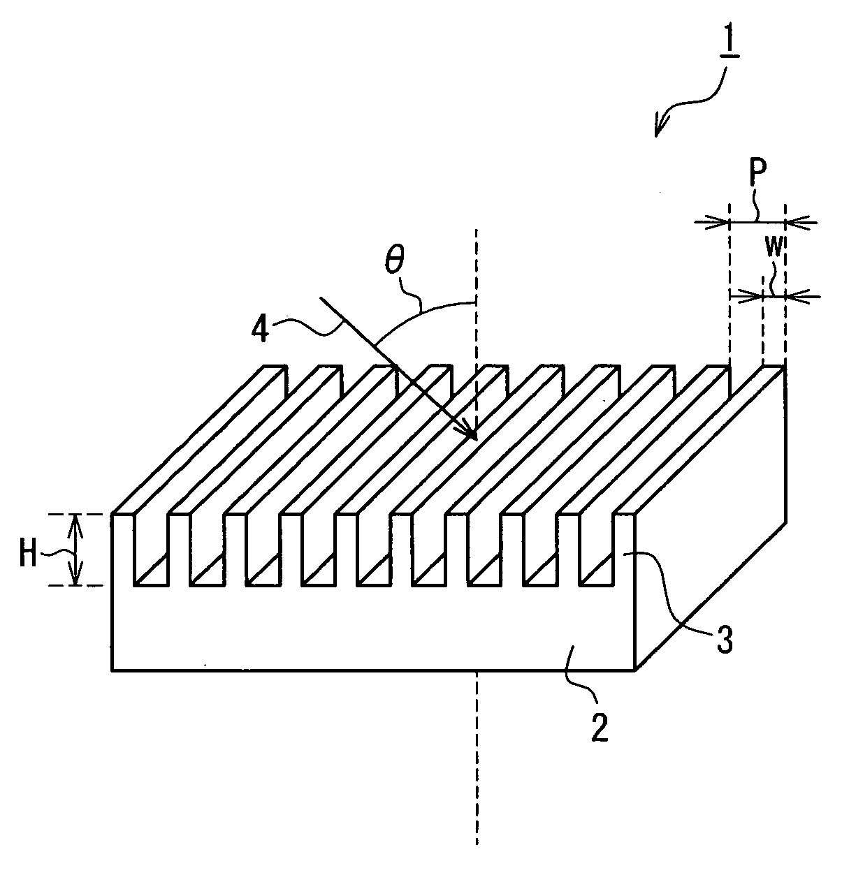
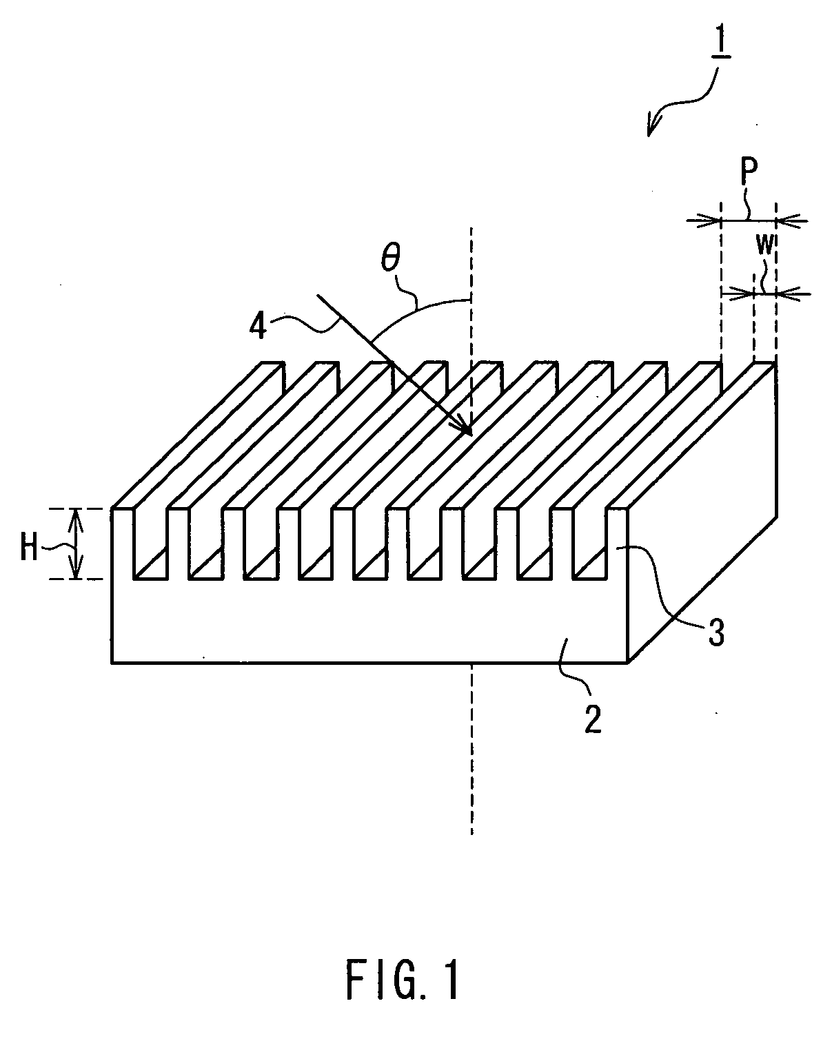
[0067]FIG. 1 is a perspective view showing a configuration of the polarization split element according to Embodiment 1 of the present invention. As shown in FIG. 1, the polarization split element 1 of Embodiment 1 is made of a transparent material, and has a periodic concavo-convex structure. Here, the period of the concavo-convex structure is set to be substantially equal to a wavelength of light to be used or less. And, the polarization split element 1 has a function of splitting polarized light beam into a zeroth-order diffracted light beam and a first-order diffracted light beam.
[0068]More specifically, the polarization split element 1 of Embodiment 1 includes a substrate 2 and a plurality of ridge-sha...
embodiment 2
[0257]Next, an optical pickup of Embodiment 2 of the present invention will be described with reference to the drawings. Incidentally, the optical pickup of Embodiment 2 is provided with the polarization split element of the present invention that is described in Embodiment 1 as the polarization beam splitter.
[0258]FIG. 19 is a schematic view showing a configuration of the optical pickup of Embodiment 2 of the present invention. As shown in FIG. 19, the optical pickup 20 of Embodiment 2 is provided with a laser diode (hereinafter, called a “LD”) 22, a polarization beam splitter (hereinafter, called a “PBS”) 23, a photodetector (hereinafter, called a “PD”) 24, a collimating lens 25, a wavelength plate 26 and an objective lens 27. Incidentally, as the PBS 23, the first polarization split element 1a or the second polarization split element 1b of Embodiment 1 is used.
[0259]The PBS 23 outputs the polarized light beams that are incident into the PBS 23 in optical paths that differ dependi...
embodiment 3
[0276]Next, an optical isolator of Embodiment 3 of the present invention will be described with reference to the drawings. Incidentally, the optical isolator of Embodiment 3 is provided with the polarization split element of the present invention that is described in Embodiment 1.
[0277]FIG. 22 is a schematic view showing a configuration of the optical isolator of Embodiment 3 of the present invention. As shown in FIG. 22, the optical isolator 30 of Embodiment 3 is provided with a polarization split element 31 and a ¼ wave plate 32. Incidentally, as the polarization split element 31, the first polarization split element 1a or the second polarization split element 1b of Embodiment 1 is used.
[0278]Next, operations of the optical isolator 30 will be described. Light beam 34 including TE polarized light beam and TM polarized light beam is incident into the polarization split element 31. The polarization split element 31 and the ¼ wave plate 32 are arranged such that only an arbitrary lin...
PUM
| Property | Measurement | Unit |
|---|---|---|
| Length | aaaaa | aaaaa |
| Efficiency | aaaaa | aaaaa |
| Efficiency | aaaaa | aaaaa |
Abstract
Description
Claims
Application Information
 - R&D Engineer
- R&D Manager
- IP Professional
- Industry Leading Data Capabilities
- Powerful AI technology
- Patent DNA Extraction
Browse by: Latest US Patents, China's latest patents, Technical Efficacy Thesaurus, Application Domain, Technology Topic, Popular Technical Reports.
© 2024 PatSnap. All rights reserved.Legal|Privacy policy|Modern Slavery Act Transparency Statement|Sitemap|About US| Contact US: help@patsnap.com