Monopole acoustic transmitter comprising a plurality of piezoelectric discs

a technology of piezoelectric discs and acoustic transmitters, which is applied in the direction of mechanical vibration separation, survey, and borehole/well accessories, etc., can solve the problems of difficult to obtain sufficient energy at the desired frequency, affecting the acoustic pressure and frequency output of the transmitter, and severe limitations, so as to maximize the acoustic pressure output and maximize the precision of measured acoustic parameters.

Active Publication Date: 2009-05-21
WEATHERFORD TECH HLDG LLC
View PDF19 Cites 19 Cited by
  • Summary
  • Abstract
  • Description
  • Claims
  • Application Information

AI Technical Summary

Benefits of technology

[0013]The stacked piezoelectric disc acoustic transmitter acts as a spring mass system. The frequency of the disc assembly is largely a function of the length of the disc assembly and the mass of the end caps attached at the ends. The length of the disc assembly can be adjusted within reasonable limits as long as the overall length does not introducing serious tool housing structural problems. The acoustic output of the disc assembly is a function of the number of disc comprising the disc assembly, the thickness and diameter of the discs, and the force applied on the stack. Furthermore, output frequency and directionality of the acoustic output can be adjusted by varying the mass and geometry of the first and second end cap masses. By maximizing acoustic pressure output at a desired frequency, a disc assembly can be configured to maximize the precision of measured acoustic parameters of interest.

Problems solved by technology

Logging-while-drilling (LWD) and measurement-while-drilling (MWD) tools impose severe limitations that affect the energy and frequency output of a monopole acoustic transmitter disposed within the wall of the tool and operating at a desired frequency.
These restrictions, in turn, affect the acoustic pressure and frequency output of the transmitter.
It is often difficult to obtain sufficient energy at the desired frequency from a transmitter consisting of a piezoelectric element.
Moreover, space required to fasten, seal, and mechanically and electrically isolate a transmitter in the wall of a logging tool of any type adds additional limiting factors to the transmitter dimensions and therefore to the transmitter outputs.
The structure required to operationally dispose the transmitter within the wall of the tool (such as a drill collar) imposes additional transmitter dimensional restrictions that, in turn, affect energy and frequency output of the transmitter.

Method used


Image

  • Monopole acoustic transmitter comprising a plurality of piezoelectric discs
  • Monopole acoustic transmitter comprising a plurality of piezoelectric discs
  • Monopole acoustic transmitter comprising a plurality of piezoelectric discs

Examples


Embodiment Construction

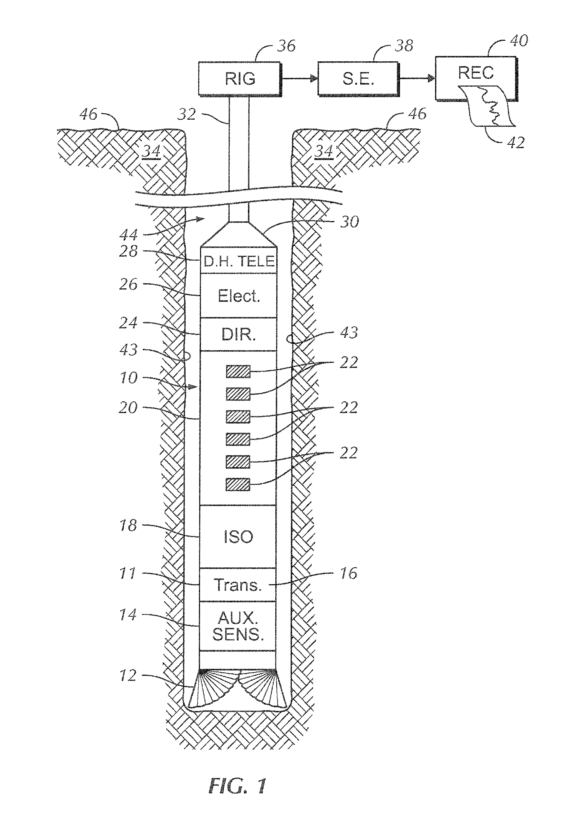
[0029]An acoustic LWD logging tool typically comprises one or more acoustic transmitters and one or more acoustic receivers.

[0030]FIG. 1 illustrates a single acoustic transmitter embodied as an LWD acoustic system disposed in a borehole drilling environment. The LWD borehole instrument or “tool” component of the borehole assembly is designated as a whole by the numeral 10, and comprises a tool pressure housing 11 which is typically a drill collar. The tool 10 is disposed within a well borehole 44 defined by borehole walls 43 and penetrating earth formation 34. A drill bit 12 terminates a lower end of the tool 10, and a connector 30 terminates an upper end of the tool. The connector 30 operationally connects the tool 10 to a lower end of a drill string 32. The upper end of the drill string terminates at a rotary drilling rig 36, which is known in the art and is illustrated conceptually at 36.

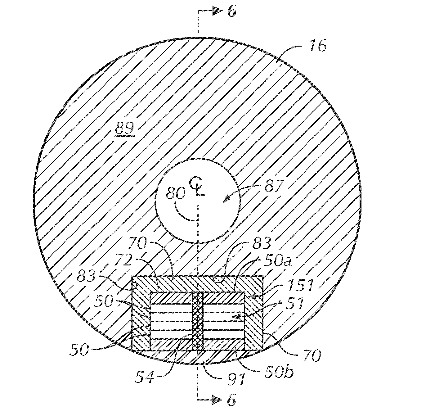
[0031]Again referring to FIG. 1, the tool 10 comprises a transmitter section 16 and a receive...


PUM


Abstract

A monopole acoustic transmitter with at least one disc assembly with a plurality of piezoelectric discs configured to optimized acoustic pressure output within a desired frequency range while meeting physical restrictions of LWD and MWD logging systems. The transmitter is disposed in a recess or “slot” in the perimeter of a logging tool housing to reduce acoustic pressure waves transmitted directly along the tool housing and to optimize acoustic energy transmission into the borehole environs. In order to increase acoustic pressure output at a desired logging frequency range, the plurality of piezoelectric discs in each of at least one disc assembly are connected electrically in parallel and fired simultaneously. The polarity of the discs and the wiring arrangement are such that each disc expands or contracts in a common direction during simultaneous firing by an applied voltage. The desired output frequency is obtained by selectively polarizing and dimensioning the discs within the one or more disc assemblies. Each disc assembly is preferably disposed within an oil filled pressure housing that is pressure and temperature compensated. The axis of the at least one disc assembly can be parallel or perpendicular to the major axis of the logging tool.

Description

FIELD OF THE INVENTION[0001]This invention is related to systems for measuring an acoustic property of material penetrated by a well borehole. More particularly, the invention is related to improved acoustic transmitters for use with acoustic logging-while-drilling (LWD) or measurement-while-drilling (MWD) borehole assemblies.BACKGROUND[0002]Acoustic logging systems are routinely used in the oil and gas industry to measure formation acoustic properties of earth formation penetrated by a well borehole. These properties include the compressional and shear velocities of the formation, which are subsequently used to determine a variety of formation parameters of interest such as porosity and pore pressure. Additionally, acoustic logging systems are used to produce acoustic images of the borehole from which well conditions and other geological features can be investigated. Other applications of acoustic logging measurements include seismic correlation and rock mechanic determination.[000...

Claims


Application Information

Patent Timeline
Patent Type & Authority Applications(United States)
IPC IPC(8): E21B47/16
CPCG01V1/40B06B1/0618B06B1/0611G01V1/52E21B47/00
Inventor JONES, DALE A.MICKAEL, MEDHAT W.
Owner WEATHERFORD TECH HLDG LLC
Why Eureka
Try Eureka