Passive emergency feedwater system

a feedwater system and emergency technology, applied in the direction of nuclear reactors, nuclear elements, greenhouse gas reduction, etc., can solve the problems of nuclear reactor b>5/b> being shut down and unable to generate electricity for an extended period of tim

Active Publication Date: 2009-05-21
NUSCALE
View PDF13 Cites 74 Cited by
  • Summary
  • Abstract
  • Description
  • Claims
  • Application Information

AI Technical Summary

Problems solved by technology

The latter two of these responses result in the nuclear reactor 5 being sh

Method used


Image

  • Passive emergency feedwater system
  • Passive emergency feedwater system
  • Passive emergency feedwater system

Examples


Embodiment Construction

[0016]Conventional nuclear facilities are expensive to license and build, with significant upfront investment costs and delayed return of profits. In addition to energy cost considerations, efficiency requirements, and reliability concerns, today's nuclear reactor designs must also take into account issues of nuclear proliferation, terrorist activities, and a heightened awareness of environmental stewardship.

[0017]Developing countries that could otherwise greatly benefit from nuclear power are frequently left to resort to other energy sources such as coal, gas or hydroelectric power generators that produce significant amounts of pollution or have other detrimental environmental impact. These developing countries may not have the technological or natural resources that enable them to build a nuclear power plant. Countries that have already developed nuclear power may be hesitant to introduce these technologies into the developing countries out of concern of the loss of control of the...


PUM


Abstract

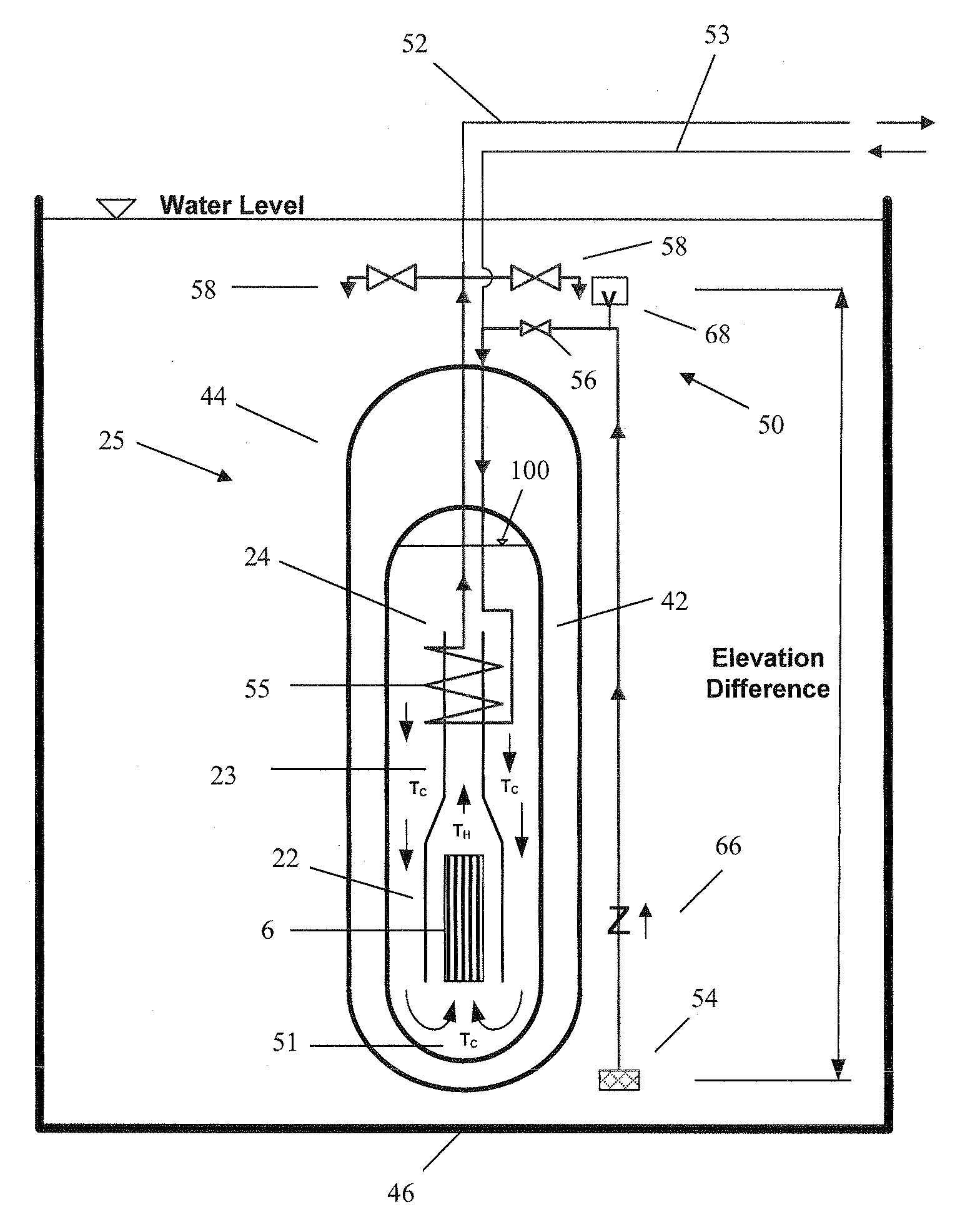
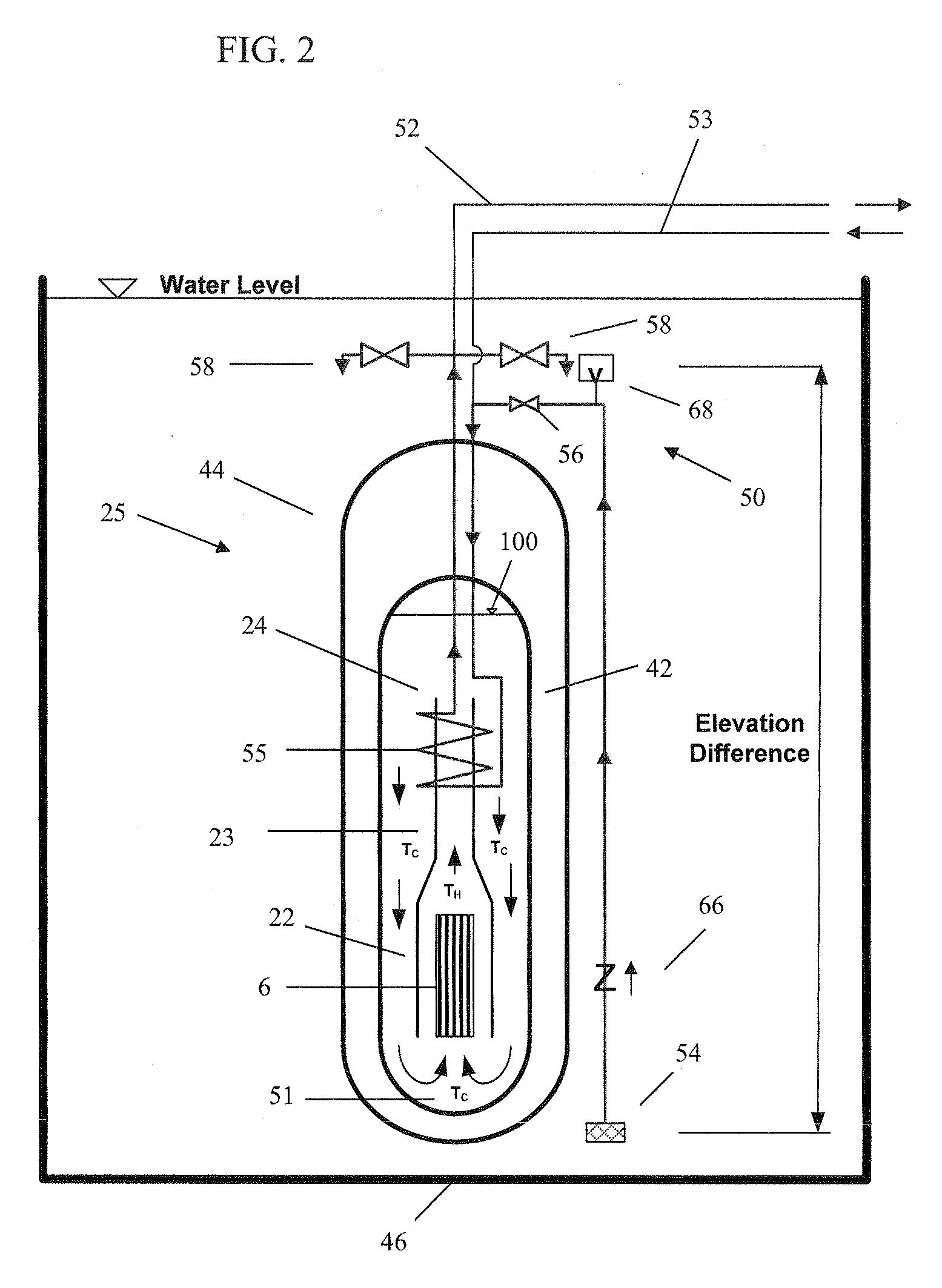
A power module assembly includes a reactor vessel containing a reactor core surrounded by a primary coolant. A containment vessel is adapted to be submerged in a containment cooling pool and to prohibit a release of the primary coolant outside of the containment vessel. A secondary cooling system is configured to remove heat generated by the reactor core. The heat is removed by circulating liquid from the containment cooling pool through the primary coolant.

Description

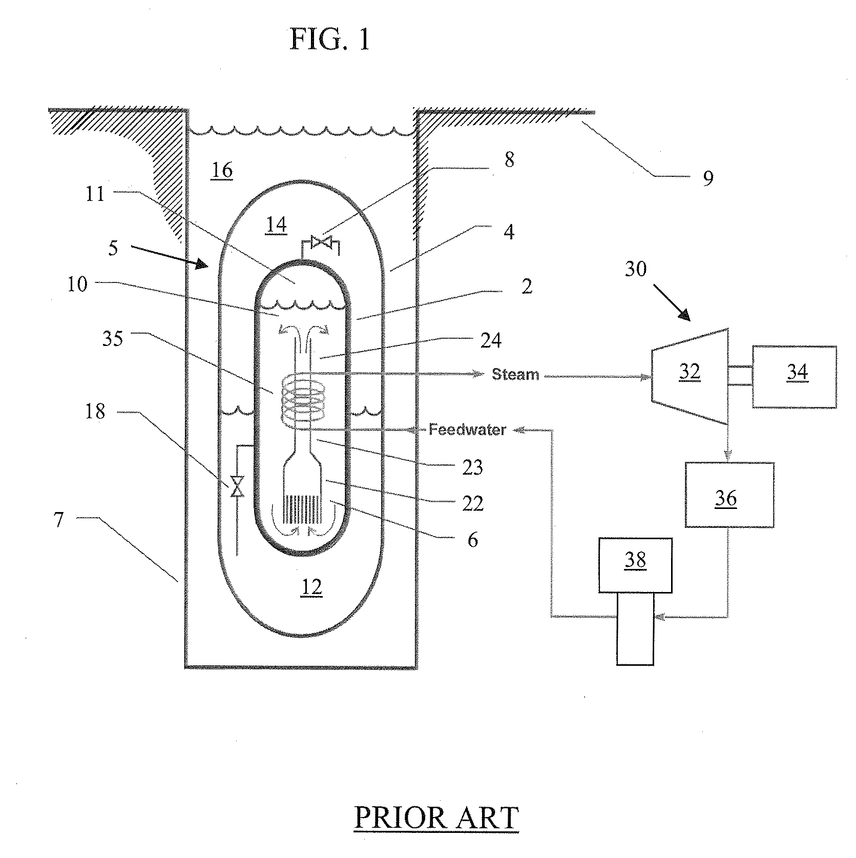
[0001]This application claims priority to U.S. Provisional Application Ser. No. 60 / 988,348 filed on Nov. 15, 2007, the specification of which is herein incorporated by reference in its entirety.TECHNICAL FIELD[0002]The invention relates to a cooling system for a nuclear reactor.BACKGROUND[0003]In nuclear reactors designed with passive operating systems, the laws of physics are employed to ensure that safe operation of the nuclear reactor is maintained during normal operation or even in an emergency condition without operator intervention or supervision, at least for some predefined period of time. A Multi-Application Small Light Water Reactor project conducted with the assistance of the Idaho National Engineering and Environmental Laboratory, NEXANT and the Nuclear Engineering Department of Oregon State University sought to develop a safe and economical natural light water reactor. FIG. 1 illustrates a nuclear reactor design 5 that resulted from this project.[0004]The nuclear reacto...

Claims


Application Information

Patent Timeline
IPC IPC(8): G21C9/00
CPCG21C1/32G21C15/18G21C15/26G21Y2002/201G21C9/012G21Y2004/30G21Y2004/40Y02E30/40G21C9/00G21Y2002/304Y02E30/30
Inventor REYES, JR., JOSE N.GROOME, JOHN T.
Owner NUSCALE
Why Eureka
Try Eureka