
Coaxial rotor system for helicopters

Inactive Publication Date: 2009-05-21
BAHADIR FUAT
View PDF5 Cites 7 Cited by
  • Summary
  • Abstract
  • Description
  • Claims
  • Application Information

AI Technical Summary

Benefits of technology

[0011]The present invention provides an improved coaxial rotor assembly for a helicopter including an upper rotor system having a multiple of upper rotor blades each having outer tips, the upper rotor blades mounted on and extending outwards from a central rotor shaft and a lower rotor system having a multiple of lower rotor blades each having outer tips and mounted on and extending outwards from the central rotor shaft. The upper rotor system is spaced an axial distance from the lower rotor system on the central rotor shaft. Finally, a rotor blade support ring extends circumferentially around each of the upper and lower rotor systems movably engaging and supporting the outer tips of the upper and lower rotor blades in spaced apart relation such that the upper and lower rotor systems rotate in opposite directions and the rotor blade support ring prevents contact between the upper and lower rotor systems during operation thereof.
[0012]The present invention thus provides a substantial improvement over those systems and methods found in the prior art which are designed to prevent the upper and lower rotors of coaxial rotor systems from accidentally interacting. First of all, because the device for maintaining separation of the upper and lower rotor systems provides a structural physical barrier to the interaction of the two rotor systems, it is superior to those devices which are designed to sense improper proximity and only then react to try to prevent the interaction. Such devices can fail, whereas the present invention cannot unless structural failure of the ring occurs. Also, because the present invention provides a circumferential ring which effectively covers the outer tips of the rotor blades, it is safer for persons working on or with the helicopter to be around the helicopter, as accidental contact with the rotating blade tips is prevented. Perhaps most importantly from an operational standpoint, however, the present invention prevents interaction of the upper and lower rotor systems during extreme operation of the helicopter, and as it is during these maneuvers that rotor interaction is most likely to take place, the present invention will permit the operator of the helicopter to concentrate on flying the helicopter and not be concerned about potential interaction between rotor systems. It is therefore seen that the present invention provides a substantial improvement over those systems and methods found on the prior art.

Problems solved by technology

Unfortunately, however, coaxial rotors have several disadvantages which must be addressed in order to permit the coaxial rotor system to function properly.
For example, there is an increased mechanical complexity of the rotor system due to the required linkages and swash plates for a dual coaxial rotor system.
Furthermore, because each rotor system needs to be turned in an opposite direction, the central rotor shaft or mast itself is far more complex, and provisions for making pitch changes to the upper rotor system must pass through the lower rotor system.
The most significant and potentially deadly problem encountered with coaxial rotor systems, however, is that during extreme aerobatic maneuvers of the helicopter, such as those encountered during combat or the like, the upper rotor system may accidentally contact the lower rotor system during operation thereof, which results in the contacting blades disintegrating due to the high rate of speed at which the upper and lower rotor systems are rotating, and this disintegration of the rotor blades results in rapid disintegration of the remaining elements of the rotor system due to the unbalanced nature of the upper and lower rotor systems, and the entire rotor structure quickly becomes unstable and self-destructs.
This, of course, results in the helicopter falling from the sky and further results in the almost certain death of the pilot and crew of the helicopter.
In fact, all of the prior art devices currently known follow a similar method of attempting to address and correct the problem of rotor tip contact between upper and lower rotor systems, but, of course, in extreme conditions, these systems can fail resulting in destruction of the upper and lower rotor systems.

Method used


Image

  • Coaxial rotor system for helicopters
  • Coaxial rotor system for helicopters
  • Coaxial rotor system for helicopters

Examples


Embodiment Construction

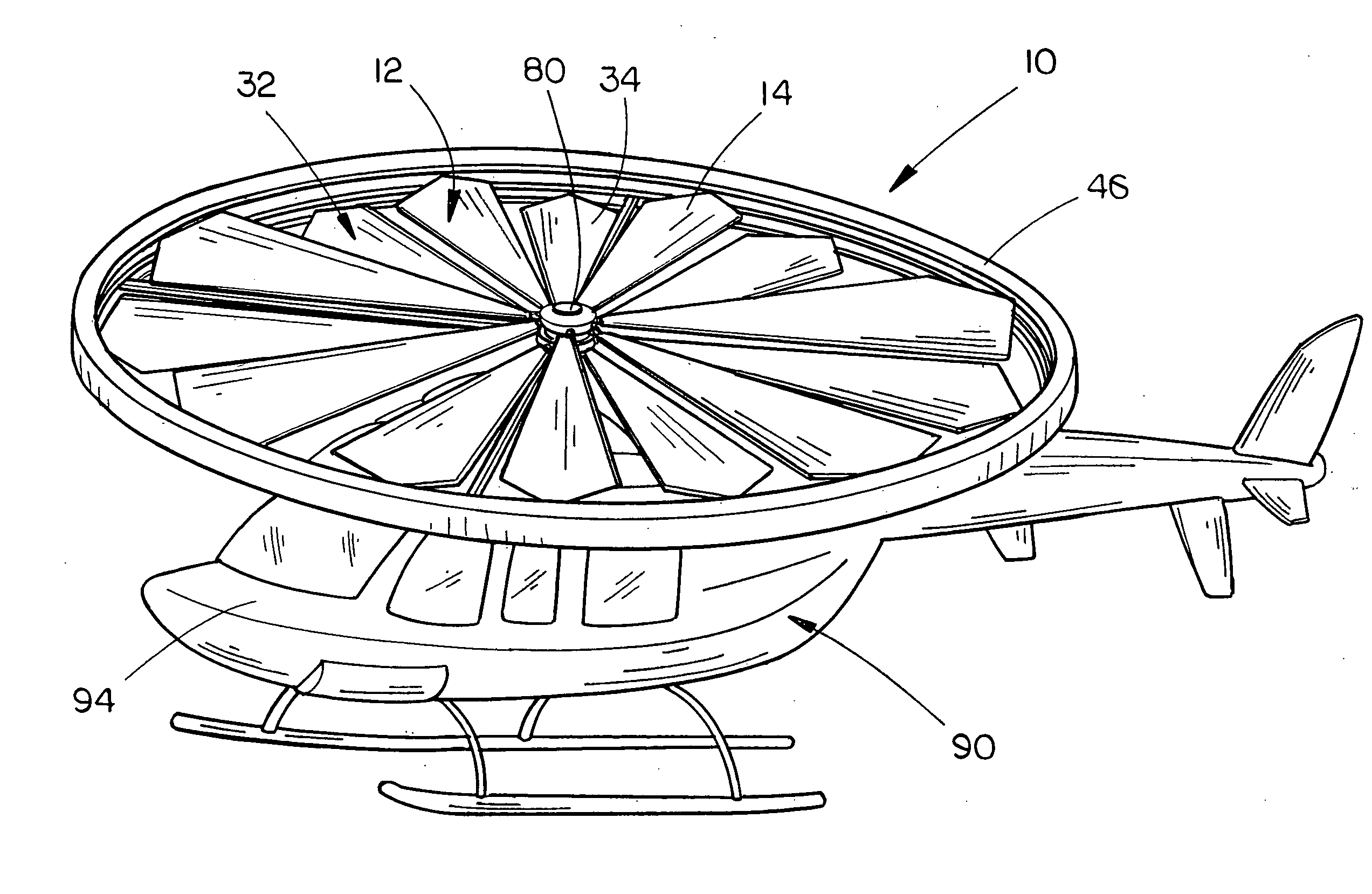
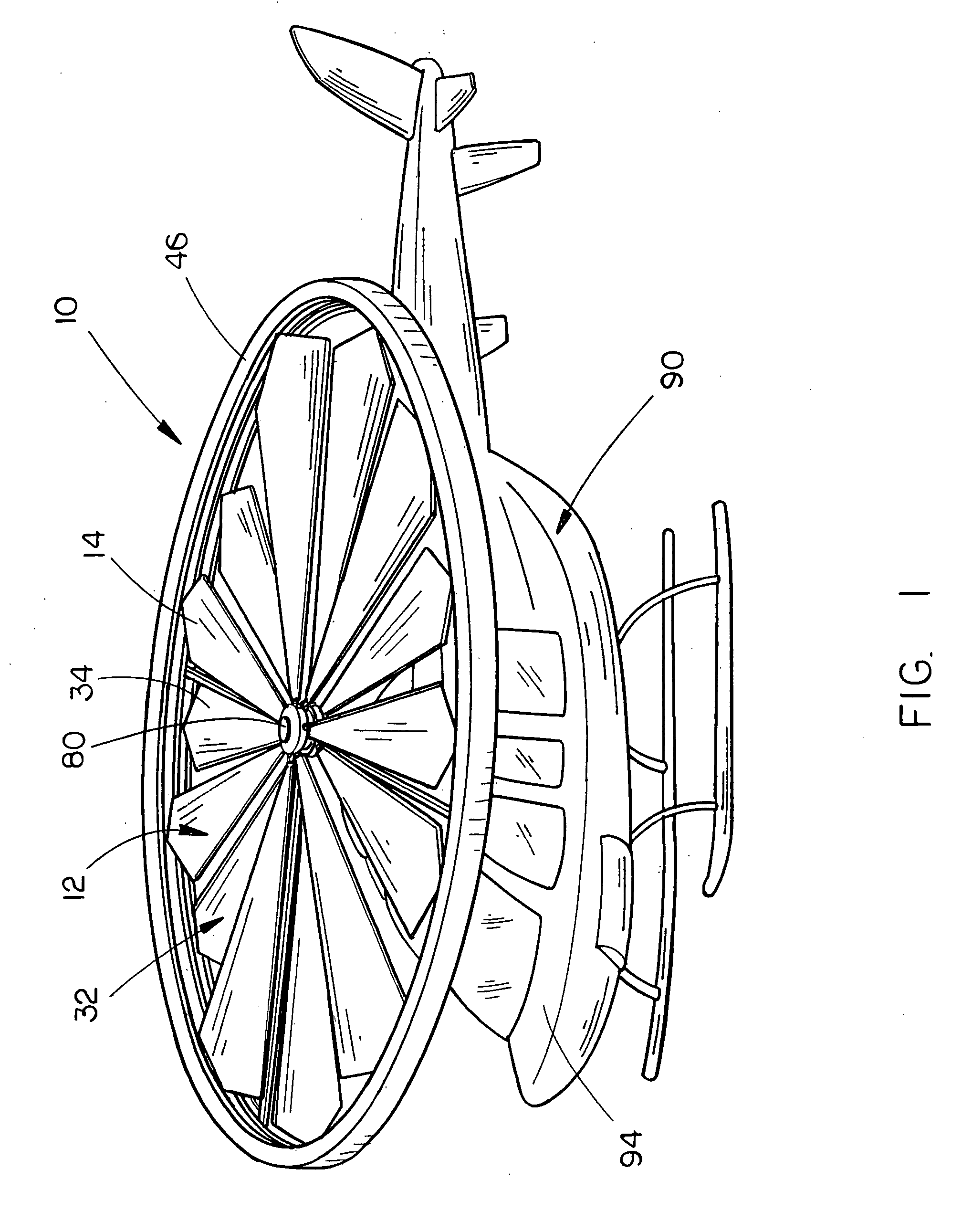
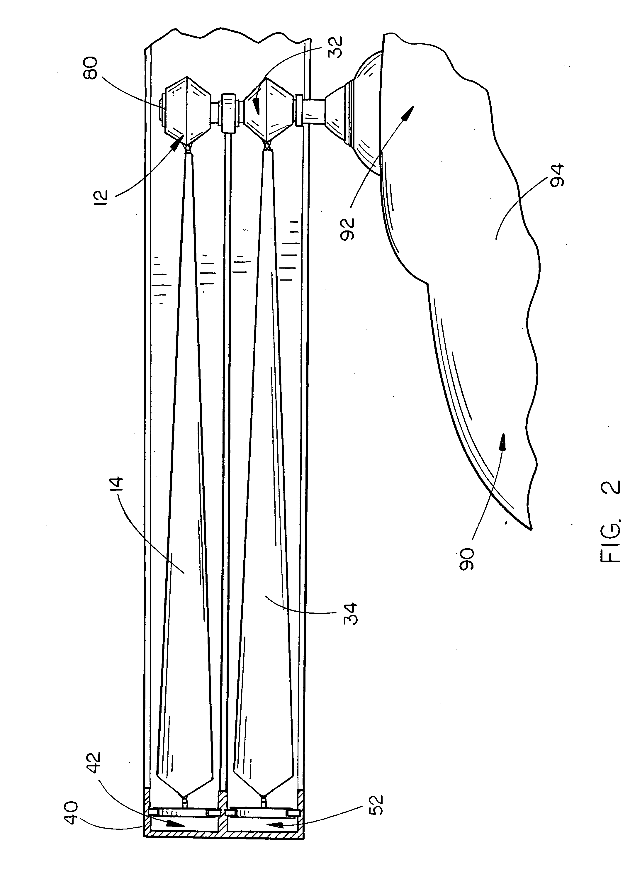
[0020]The improved coaxial rotor assembly 10 of the present invention is shown best in FIGS. 1-5 as including an upper rotor system 12 and a lower rotor system 32 each of which include a plurality of rotor blades, specifically a set of upper rotor blades 14 and a set of lower rotor blades 34. In the preferred embodiment, the upper and lower rotor systems 12 and 32 would each include approximately three to eight rotor blades 14 and 34, with the exact number, shape and size of the rotor blades to be determined by the specific design and performance requirements of the helicopter 90 with which the improved helicopter rotor assembly 10 of the present invention is to be used.

[0021]Of course, the improved helicopter rotor assembly 10 of the present invention would include all of the standard elements found in coaxial rotor assemblies, including the various control elements which control the pitch and yaw of the upper and lower rotor systems 12 and 32 and the power plant 92 operative to dr...


PUM


Abstract

An improved coaxial rotor assembly for a helicopter includes an upper rotor system having a multiple of upper rotor blades each having outer tips and mounted on and extending outwards from a central rotor shaft and a lower rotor system having a multiple of lower rotor blades each having outer tips and mounted on and extending outwards from the central rotor shaft with the upper rotor system spaced an axial distance from the lower rotor system on the central rotor shaft. A rotor blade support ring extends circumferentially around each of the upper and lower rotor systems which movably engages and supports the outer tips of the upper and lower rotor blades in spaced apart relation such that the upper and lower rotor systems rotate in opposite directions and the rotor blade support ring means prevents contact between the upper and lower rotor systems during operation thereof.

Description

BACKGROUND OF THE INVENTION[0001]1. Technical Field[0002]The present invention relates generally to improved rotor designs for helicopters and, more particularly, to an improved coaxial rotor system for helicopters which includes an upper rotor system having a plurality of upper rotor blades which are mounted on and extend outwards from a central rotor shaft, a lower rotor system having a plurality of lower rotor blades extending outwards from and connected to the central rotor shaft and rotating in a direction opposite the upper rotor system, the upper rotor system spaced an axial distance from the lower rotor system, and a circumferential rotor blade support ring which extends around the upper and lower rotor systems and engages the outer ends of each of the upper and lower rotor blades in generally parallel travel planes thereby preventing engagement of the upper rotor system with the lower rotor system during operation of the helicopter.[0003]2. Description of the Prior Art[0004...

Claims


Application Information

Patent Timeline
IPC IPC(8): F01D5/02
CPCB64C27/32B64C27/10
Inventor BAHADIR, FUAT
Owner BAHADIR FUAT
Learn More