High temperature refractory coatings for ceramic substrates

a ceramic substrate and high temperature technology, applied in the field of protective coatings, can solve the problems of increasing the likelihood of premature failure of the component, reducing the effectiveness of protective coatings, and not performing well at temperatures exceeding 3000°

Active Publication Date: 2009-05-21
RTX CORP
View PDF17 Cites 17 Cited by
  • Summary
  • Abstract
  • Description
  • Claims
  • Application Information

AI Technical Summary

Problems solved by technology

(650° C.) and become less effective as protective coatings.
However, while silicide containing layers may improve the temperature capability of the coating, they do not perform well at temperatures exceeding 3000° F.
Also, under certain situations such as high Mach environments, glass-based coatings could erode off the component surface, thereby being non-protective, and thus increasing the likelihood of premature failure of the component.

Method used


Image

  • High temperature refractory coatings for ceramic substrates
  • High temperature refractory coatings for ceramic substrates

Examples


Embodiment Construction

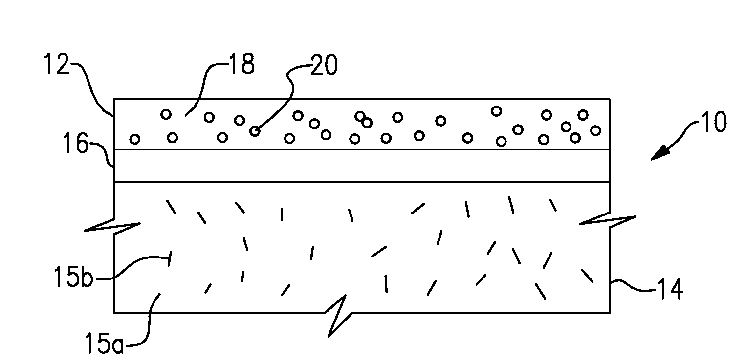
[0012]FIG. 1 illustrates selected portions of an example composite article 10 having a protective layer 12. Several non-limiting examples of potential applications of the composite article 10 include components for aerospace, hypersonics, rockets, scramjets, functionally graded ceramic structures, catalytic structures, reactors, airfoils, and heat exchangers.

[0013]In the disclosed example, the protective layer 12 is disposed on a substrate 14. Optionally, a silicate layer 16 is disposed between the protective layer 12 and the substrate 14. In one example, the silicate layer 16 includes borosilicate glass. For example, the borosilicate glass includes a composition disclosed in co-pending application Ser. No. 11 / 603,622.

[0014]In the disclosed example, the substrate 14 is a ceramic matrix composite that includes a carbon matrix 15a and silicon carbide reinforcement 15b within the carbon matrix 15a. Although a particular type of ceramic matrix composite and composite structure are discl...


PUM

PropertyMeasurementUnit
temperatureaaaaaaaaaa
temperaturesaaaaaaaaaa
temperatureaaaaaaaaaa

Abstract

A composite article includes a substrate and a protective layer on the substrate. The protective layer includes a non-oxide ceramic matrix and a refractory phase within the non-oxide ceramic matrix.

Description

[0001]This invention was made with government support under Contract No. F33615-01-D-5802, Subcontract No. S-709-020-001 awarded by the United States Air Force. The government therefore has certain rights in this invention.BACKGROUND OF THE INVENTION[0002]This invention relates to protective coatings and, more particularly, to ceramic composite protective coatings and methods of manufacture.[0003]Components, such as aerospace components, typically utilize protective coatings to protect the component from detrimental effects caused by high temperatures and corrosive or erosive conditions. For example, aerospace components typically include one or more coating layers that resist oxidation of the underlying component to thereby enhance durability or maintain efficient operation of the component.[0004]Types of protective coatings that are used to protect ceramic components are silica and silica-containing glasses. Although effective at relatively low temperatures, the silica and silica-...

Claims


Application Information

Patent Timeline
Patent Type & Authority Applications(United States)
IPC IPC(8): B32B18/00C04B35/482C04B35/14C04B35/58C04B35/56C04B35/565
CPCC04B35/56Y10T428/30C04B37/005C04B38/0022C04B41/5053C04B41/52C04B41/87C04B41/89C04B2111/00551C04B2111/00982C04B2235/3804C04B2235/3817C04B2235/3891C04B2235/404C04B2235/421C04B2235/428C04B2235/483C04B2235/486C04B2237/10C04B2237/365C04B35/571C04B24/00C09D5/00C04B38/0051C04B38/007C04B41/4535C04B41/455C04B41/4554C04B41/5025C04B41/5022C04B41/5071
Inventor SCHMIDT, WAYDE R.BHATIA, TANIATANG, XIAJARMON, DAVID C.DONAHUE, OWEN B.
Owner RTX CORP
Why Eureka
Try Eureka