Device And Methods For Reducing Cardiac Valve Regurgitation

a technology of cardiac valve and valve cusp, which is applied in the field of devices and methods for reducing cardiac valve regurgitation, can solve the problems of valve regurgitation not desirable, valve prolapse or fall back, etc., and achieve the effects of reducing or preventing valve regurgitation, reducing body size, and reducing valve regurgitation

Active Publication Date: 2009-05-21
MAYO FOUND FOR MEDICAL EDUCATION & RES
View PDF10 Cites 141 Cited by
  • Summary
  • Abstract
  • Description
  • Claims
  • Application Information

AI Technical Summary

Benefits of technology

[0006]The present invention provides devices and methods that may be used to reduce valve regurgitation. The devices may preferably be implantable such that they can remain in place within a subject for extended periods of time.
[0007]The present invention preferably provides a device with an appropriately sized and shaped body that can be placed across a regurgitant valve so that, when the valve closes, the body obliterates/ameliorates the regurgitant orifice in the valve, thereby reducing or preventing valve regurgitation.
[0008]It may be preferred that the shape of the body be such that when the valve closes, the body itself provides support to the valve leaflets or cusps. It is anticipated that in some situations (particularly when regurgitation is functional due to annular dilatation) reverse remodeling of the volume overloaded chamber may occur such that the regurgitation may decrease over time as the annular dilatation recedes permitting reduction in

Problems solved by technology

Also, the leaflets or cusps of a valve can prolapse (or fall back) as a result of stretching or

Method used


Image

  • Device And Methods For Reducing Cardiac Valve Regurgitation
  • Device And Methods For Reducing Cardiac Valve Regurgitation
  • Device And Methods For Reducing Cardiac Valve Regurgitation

Examples


Embodiment Construction

[0034]In the following detailed description of some exemplary embodiments of the invention, reference is made to the accompanying figures which form a part hereof, and in which are shown, by way of illustration, specific embodiments in which the invention may be practiced. It is to be understood that other embodiments may be utilized and structural changes may be made without departing from the scope of the present invention.

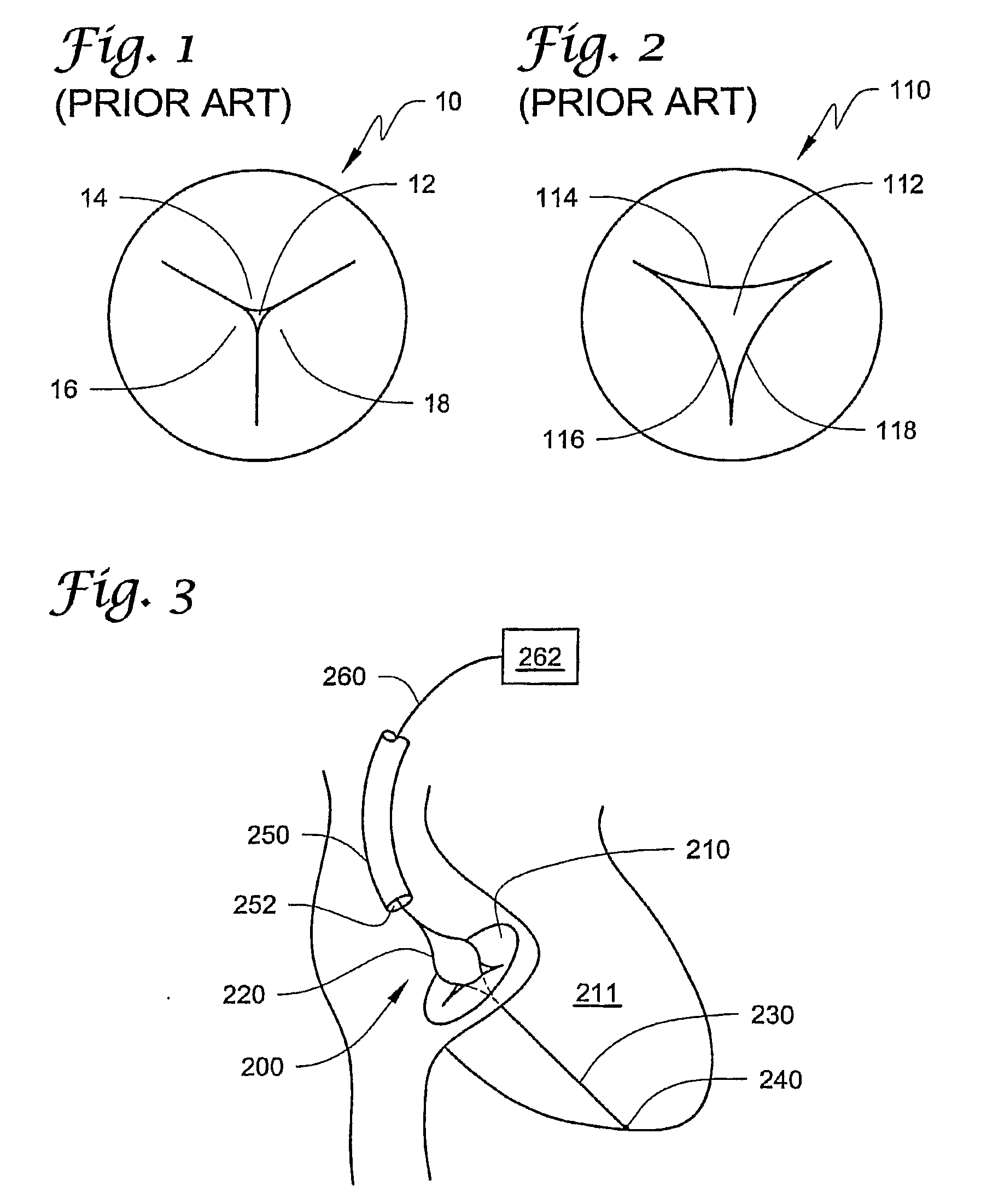
[0035]FIGS. 1 & 2 depict tricuspid valves, with the valve 10 in FIG. 1 being a competent valve in the closed position in which the valve 10 essentially prevents backflow with leaflets or cusps 14, 16&18 that act together to close the opening 12.

[0036]In contrast, FIG. 2 depicts a tricuspid valve 110 that includes a regurgitant orifice 112 that is not closed by the leaflets or cusps 114, 116&118. Backflow through the regurgitant orifice 112 in the valve 110 may, however, be reduced using the devices and methods of the present invention.

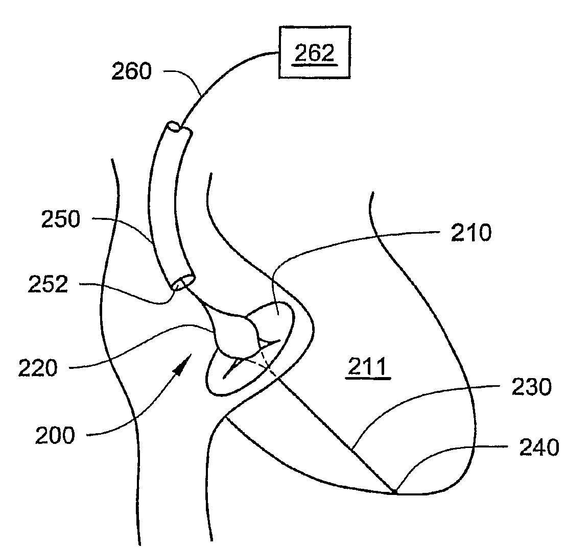
[0037]FIG. 3 depicts deploy...


PUM


Abstract

Devices and methods that may be used to reduce valve regurgitation are disclosed by locating a body across the regurgitant valve. When the valve closes, the body obliterates/ameliorates the regurgitant orifice in the valve, thereby reducing or preventing valve regurgitation. The body may be expandable. The devices may be implantable such that they can remain in place within a subject for extended periods of time.

Description

RELATED APPLICATION[0001]The present application claims the benefit under 35 U.S.C. § 119(e) of U.S. Provisional Patent Application No. 60 / 683,089, filed May 20, 2005 and titled DEVICES AND METHODS FOR REDUCING CARDIAC VALVE REGURGITATION, which is hereby incorporated by reference in its entirety.[0002]The present invention relates to devices and methods for reducing cardiac valve regurgitation, more particularly, the present invention provides expandable devices designed to limit flow through a leaking cardiac valve and methods of using those devices.[0003]There are four valves in the human heart. The mitral and tricuspid valves are situated between the left atrium and ventricle and between the right atrium and ventricle respectively. The aortic valve is between the left ventricle and the aorta, and the pulmonary valve is situated between the right ventricle and the pulmonary artery. Heart valves include a fibrous frame (or annulus) and moveable leaflets or cusps.[0004]Valvular reg...

Claims


Application Information

Patent Timeline
IPC IPC(8): A61M25/00A61M31/00
CPCA61F2/246A61F2250/0003
Inventor SPEZIALI, GIOVANNIBRUCE, CHARLES
Owner MAYO FOUND FOR MEDICAL EDUCATION & RES
Why Eureka
Try Eureka