

Stent crimping apparatus
a crimping device and stent technology, applied in the field of stents or vascular prosthesis crimping devices, can solve the problems of difficult to judge when or if a uniform and reliable crimping had been applied, block the flow of blood, and non-uniform crimping, so as to facilitate the even movement of the catheter and facilitate the effect of rigidity
- Summary
- Abstract
- Description
- Claims
- Application Information
AI Technical Summary
Benefits of technology
Problems solved by technology
Method used
Image

Examples
Embodiment Construction
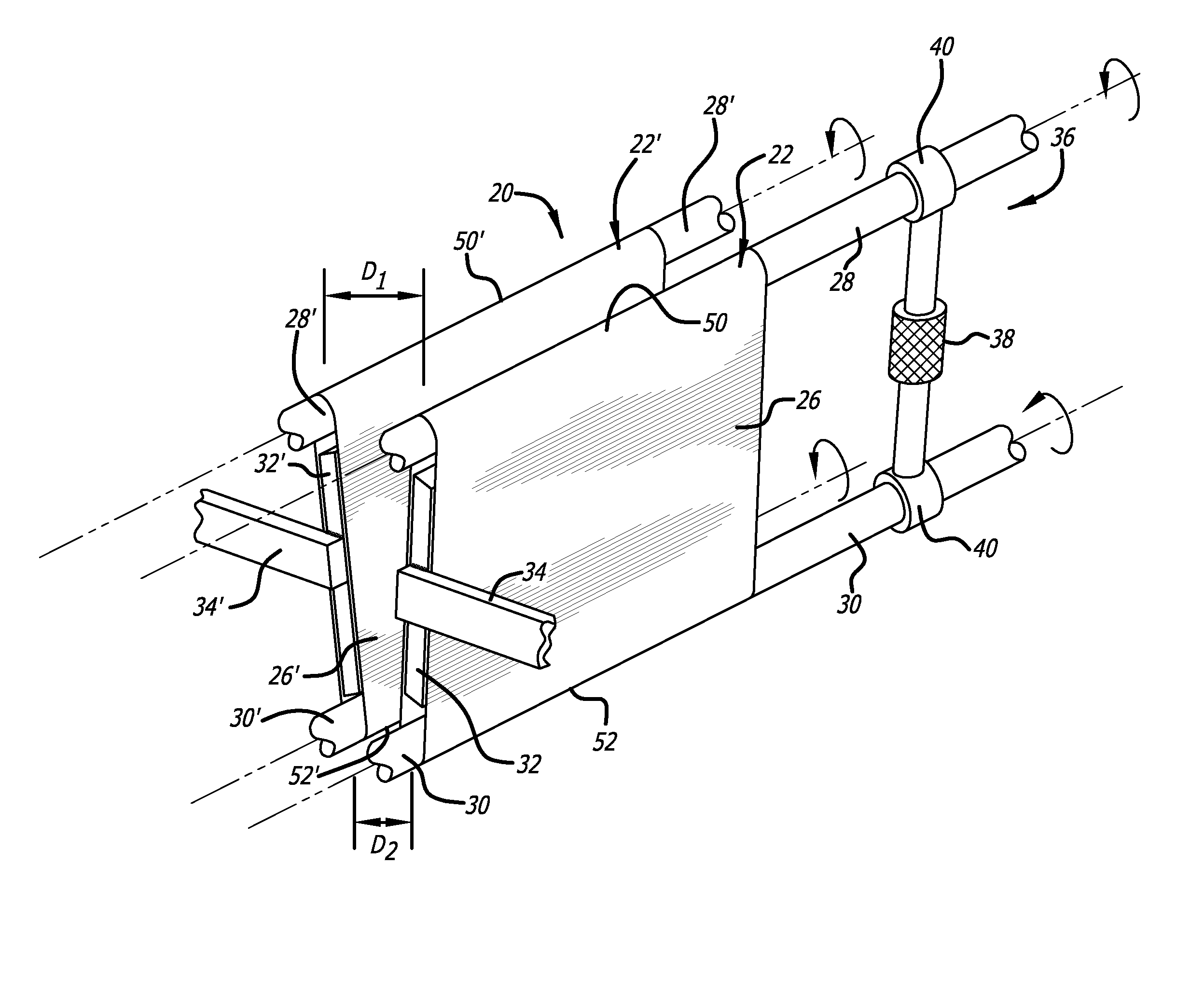
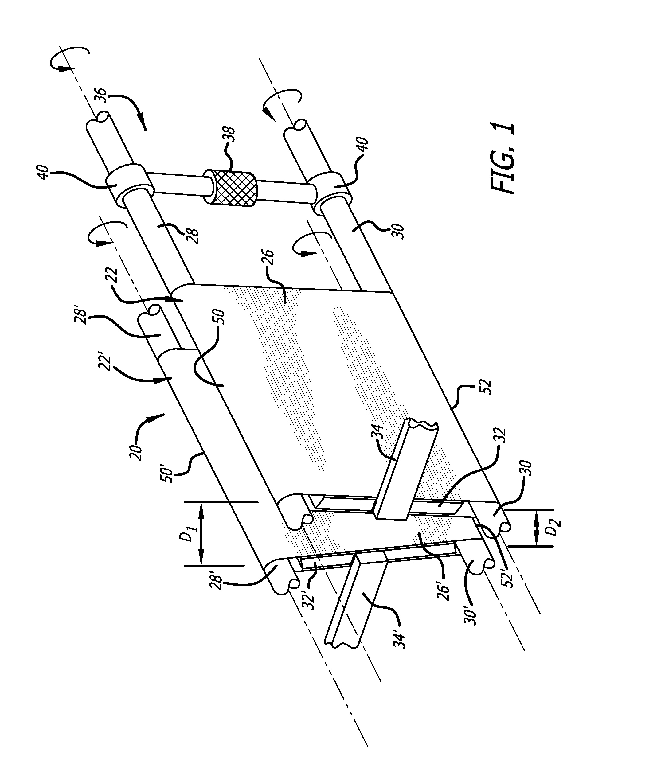
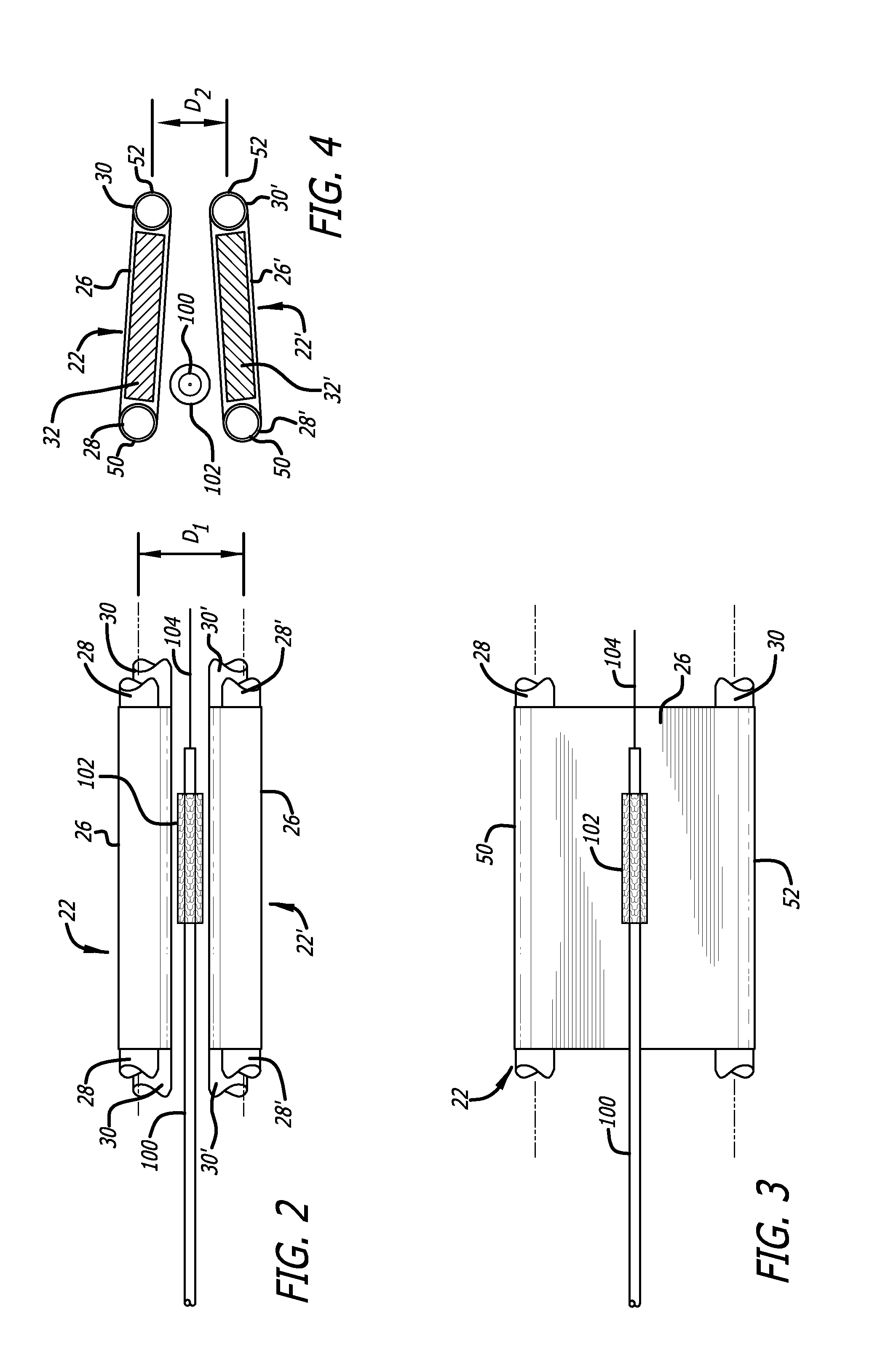
[0020]With reference to the drawings, which are provided by way of exemplification and not limitation, a stent crimping device is described having features of the present invention. In a preferred embodiment, a stent crimping device, generally identified by the numeral 20, includes two mirror image pressure walls 22, 22′ positioned to oppose each other. Each pressure wall is configured to impart a radially inward force, and also a rotational force, on a stent located upon a catheter, as more fully set forth herein.
[0021]Each pressure wall includes an upper cylindrical bar 28, 28′ and a lower cylindrical bar 30, 30′. Each one of the four bars is configured to rotate upon its axis. In a preferred embodiment, one set of bars (the upper bars 28, 28′ or the lower bars 30, 30′) may be rotated under the power of a motor (not shown), although in an alternative embodiment both sets of bars may be rotated under power. Further included in each pressure wall, a flexible belt 26, 26′ is tightly ...
PUM
 Abstract
Description
Claims
Application Information