Vascular Prosthesis for Aneurysms, Set of Vascular Prostheses, Method for Manufacturing a Vascular Prosthesis and Method for Inserting a Vascular Prosthesis

a technology for aneurysms and vascular prostheses, which is applied in the field of vascular prostheses, can solve problems such as the patient's subsequent bleeding to death, and achieve the effect of reducing radial and longitudinal stress on the healthy vessel portion

Inactive Publication Date: 2009-05-21
BERKHOFF WOLFGANG
View PDF7 Cites 49 Cited by
  • Summary
  • Abstract
  • Description
  • Claims
  • Application Information

AI Technical Summary

Benefits of technology

[0007]Accordingly, one aspect is to provide an improved vascular prosthesis for aneurysms tha...

Problems solved by technology

The main risk lies, in fact, in a potential rupture of the un...

Method used


Image

  • Vascular Prosthesis for Aneurysms, Set of Vascular Prostheses, Method for Manufacturing a Vascular Prosthesis and Method for Inserting a Vascular Prosthesis
  • Vascular Prosthesis for Aneurysms, Set of Vascular Prostheses, Method for Manufacturing a Vascular Prosthesis and Method for Inserting a Vascular Prosthesis
  • Vascular Prosthesis for Aneurysms, Set of Vascular Prostheses, Method for Manufacturing a Vascular Prosthesis and Method for Inserting a Vascular Prosthesis

Examples


second embodiment

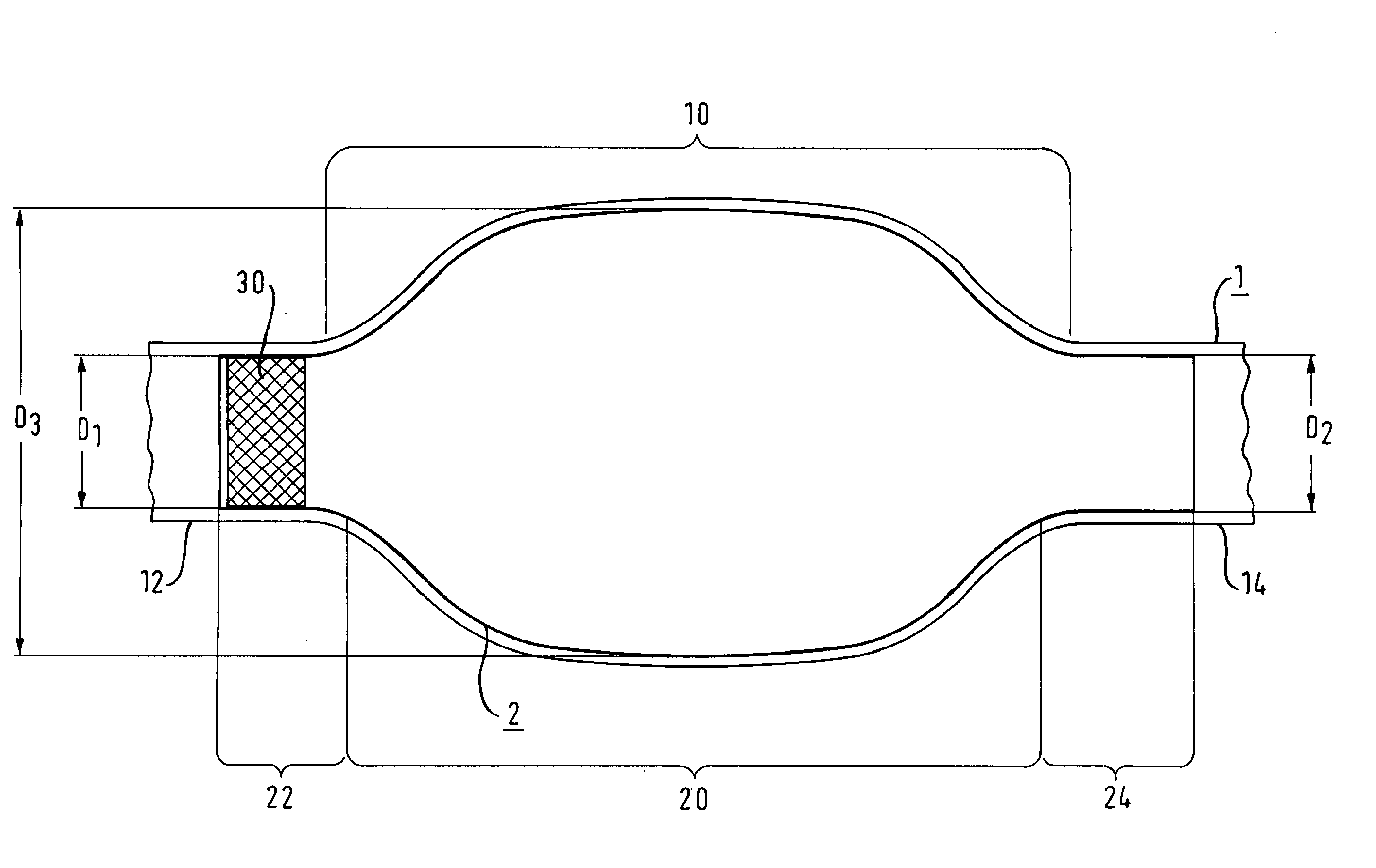
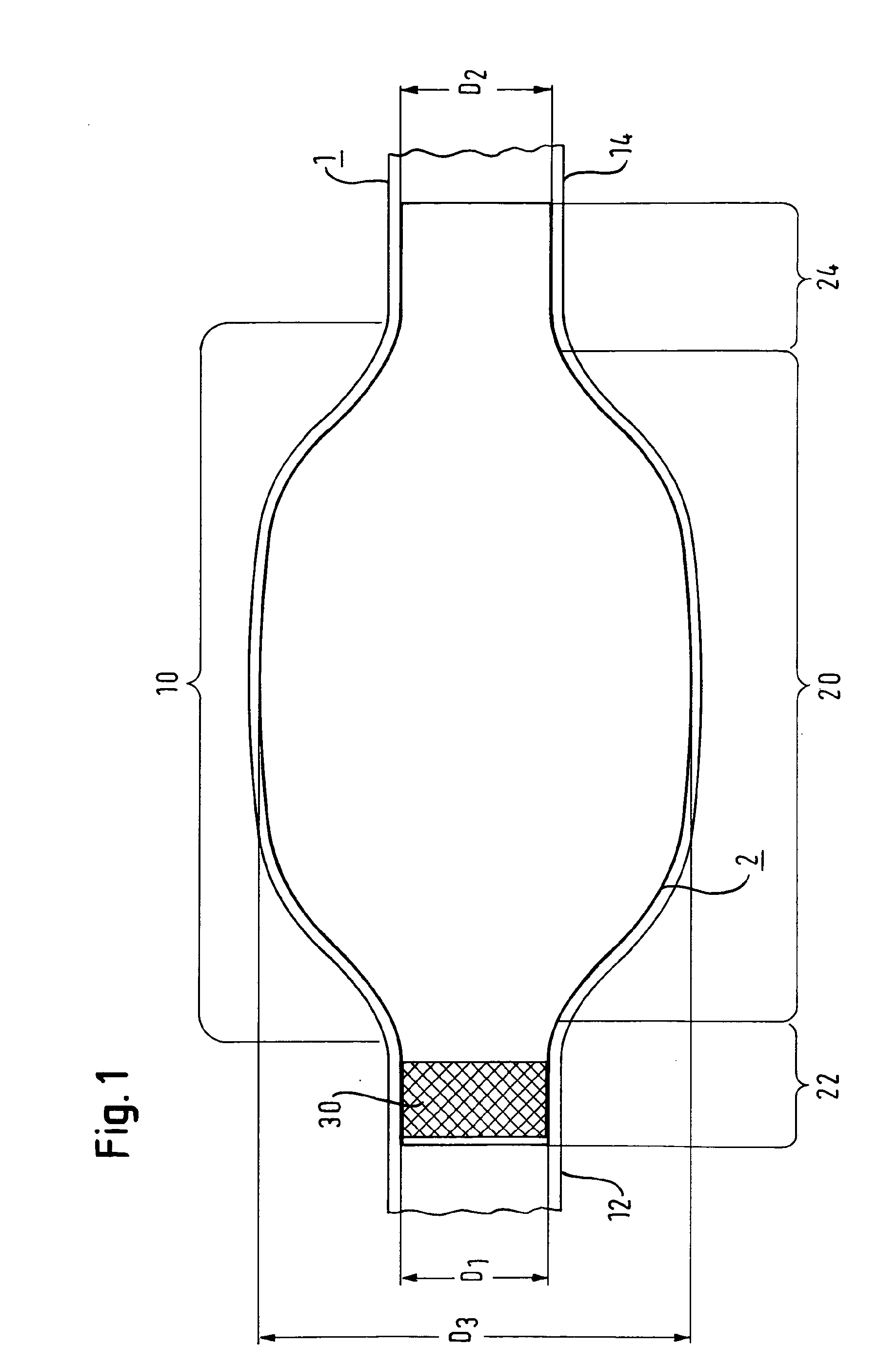
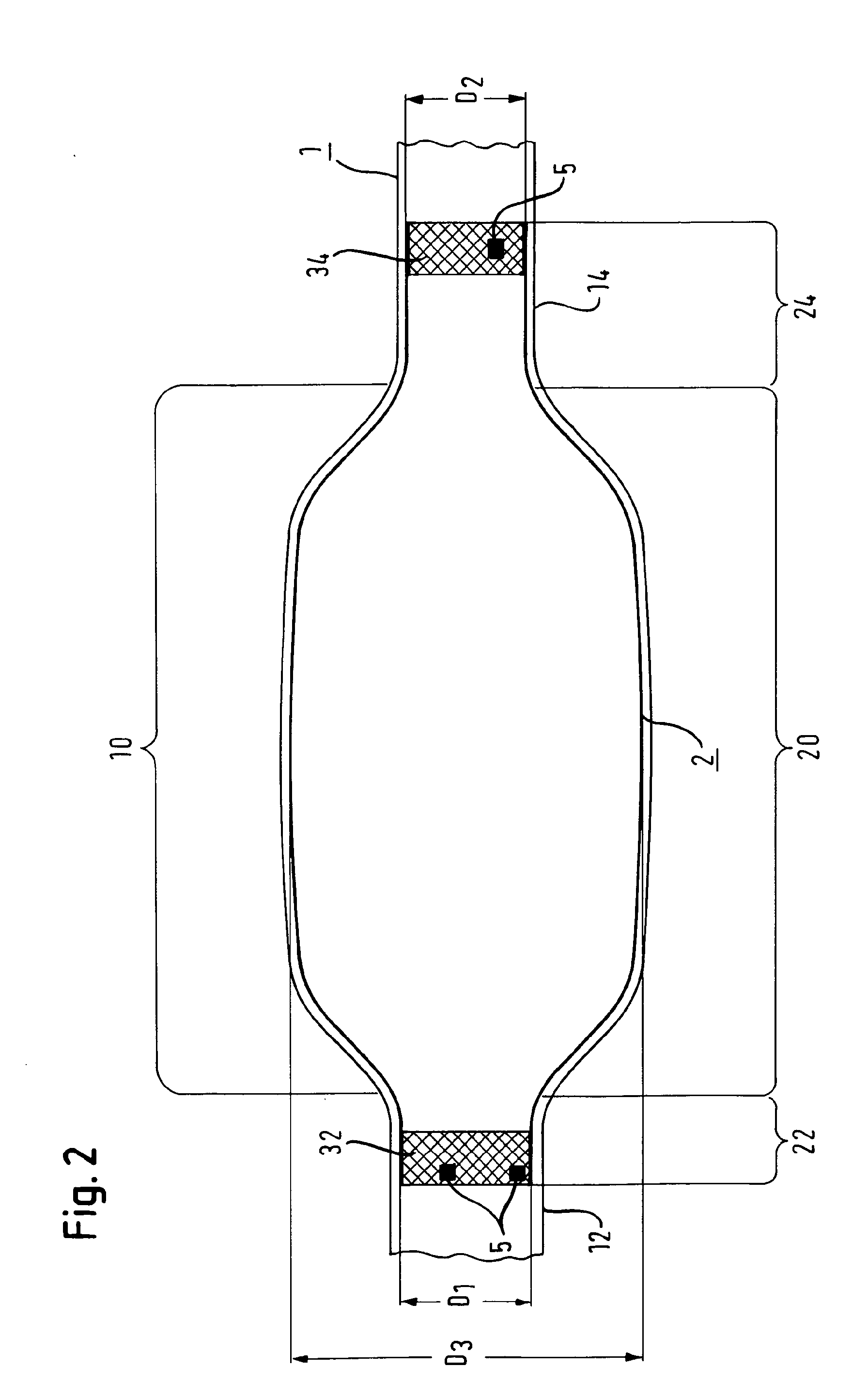
[0050]FIG. 2 shows an aorta 1 with an aneurysm 10 in a liner 2. The liner basically has the same characteristics as that described to FIG. 1, namely, a first terminal sleeve portion 22, a second terminal sleeve portion 24 and a body portion 20. The first terminal sleeve portion 22 has a first diameter D1, the second terminal sleeve portion 24 has a second diameter D2 and the body portion 20 has a body diameter D3. The body diameter D3 is larger than the diameter D1 of the first terminal sleeve portion 22 as well as the second diameter D2 of the second terminal end portion 24.

[0051]In this second embodiment, however, the sleeve carries a first anchor 32 in the area of the first terminal sleeve portion 22 and a second anchor 34 in the area of the second terminal sleeve portion 24. Furthermore, the first anchor 32 and the second anchor 34 are fixedly attached to the terminal end portions 22 and 24 of the liner 2. In this embodiment, an even better fixing of the liner 2 in the desired p...

third embodiment

[0054]FIG. 4 shows a vascular prosthesis in a third embodiment in which the liner 2 has, in its body portion 20, sections 200, 202, 204 of different diameters which are connected by bending portions 201, 203. A body portion according to this embodiment can resemble the shape of an aneurysm more closely.

[0055]In the embodiment shown, it is only necessary to measure the aneurysm to be treated in three different positions in order to determine the diameters of the sections 200, 202 and 204 to manufacture the liner 2. Furthermore, to manufacture the liner 2 of the vascular prosthesis, it is preferred to measure the diameters of the first terminal sleeve portion and the second terminal sleeve portion as well. In order to fit the liner 2 to an actual inner shape of an aneurysm sack more precisely, in this specific embodiment only five measurements of the spatial dimensions of the aneurysm sack and the adjacent vessels have to be carried out. This results in an easy manufacturing process a...


PUM


Abstract

The present invention relates to a vascular prosthesis for aneurysms (10, 10′) comprising a liner (2, 2′) that defines a lumen, the liner having at least a first terminal sleeve portion (22, 22′) with a first diameter (D1), at least a second terminal sleeve portion (24, 24′, 26′) with a second diameter (D2) and a body portion (20, 20′) extending between the first terminal sleeve portion and the second terminal sleeve portion, the body portion having at least one body diameter (D3) that is larger than the first diameter and the second diameter.

Description

FIELD OF THE INVENTION[0001]The present invention relates to a vascular prosthesis to be inserted into a body vessel, in particular to treat an aneurysm, to a set of vascular prostheses, to a method for manufacturing a vascular prosthesis and to a method for inserting such vascular prosthesis.TECHNICAL BACKGROUND[0002]An aneurysm is a sac formed by the abnormal dilation of the wall of an artery, a vein or any other bodily lumen. Complications which arise from aneurysms are, above all, the risk of a rupture of the aneurysm and the quick consequent fatal bleeding of the patient. Connected to aneurysms, there are also risks of peripheral embolization from the intramural thrombus coverage of an aneurysm and phistolarization. The existence of an aneurysm can also result in the patient immediately feeling unwell due to the space requirements of the aneurysm that exerts pressure on the surrounding structures such as tissue, bone or nerve structures. Such complications include pyloric steno...

Claims


Application Information

Patent Timeline
IPC IPC(8): A61F2/44A61B19/00A61F2/06A61F2/07
CPCA61F2/07A61F2002/065A61F2/90A61F2/89A61F2250/0039
Inventor BERKHOFF, WOLFGANG
Owner BERKHOFF WOLFGANG
Why Eureka
Try Eureka