
Control device for plant, control device for thermal power plant, and gas concentration estimation device of coal-burning boiler

Active Publication Date: 2009-05-21
HITACHI LTD
View PDF13 Cites 32 Cited by
  • Summary
  • Abstract
  • Description
  • Claims
  • Application Information

AI Technical Summary

Benefits of technology

[0044]According to the present invention as an embodiment, it is possible to realize a control device for a plant and a control device for a thermal power plant each capable of preferably maintaining the control characteristic of the plant even in the case in which the characteristic of the model for predicting the characteristic of the plant as a controlled object is different from the characteristic of the actual plant.
[0045]According to the present invention as another embodiment, it is possible to realize a gas concentration estimation device of a coal-burning boiler and a gas concentration estimation method each suppressing an estimation error of a neural-network model caused by a measurement error included in actual equipment data in the case in which the variation in the concentration of CO or the concentration of NOx in the exhaust gas is simulated using a neural network in combustion control of the coal-burning boiler, thereby making it possible to estimate the gas concentration with high accuracy.

Problems solved by technology

However, in the case in which the plant is operated in an unexpected condition such as a change in the operation mode of the plant or a change in the environment, some operation such as modification of the control logic is required in some cases.
The amounts of production of CO and NOx included in the exhaust gas of the coal-burning boiler correlate inversely with each other, and when burning coal in the coal-burning boiler, if the air (oxygen) for combustion is excessively supplied, the amount of production of NOx increases, and if the air supply is insufficient to the contrary, the amount of production of CO increases.
Therefore, even if the manipulation conditions are optimum in the predicted value of the model, the manipulation conditions are not optimum for the actual plant, and consequently, the plant cannot properly controlled with these manipulation conditions.
However, according to the method described above, it requires a long period of time to accumulate the measurement data of the actual plant necessary for correcting the model, moreover, the expected control performance is not exerted during the period for accumulating the data.
However, in the case in which it is attempted to learn the static characteristic of the plant, an error is caused in modeling by using such actual equipment data including the transitional state to the learning.
Further, in general, measurement values of the plant include a measurement error.
For example, although the temperature or the like can be measured with high accuracy, the flow rate or the like is apt to include a measurement error.
Further, the age deterioration in sensors also cause a measurement error.
Therefore, there are mixed data with high accuracy and data with low accuracy including a large error in the actual equipment data.
If the learning of the neural network is performed using the actual equipment data including such data with low accuracy mixed thereto, the model of the neural network thus constructed also has low accuracy.
As a result, in the case in which the estimation model of the concentrations of CO and NOx included in the exhaust gas emitted from the coal-burning boiler as a controlled object by learning the trend of the actual equipment data using the actual equipment data including the data with low accuracy mixed thereto, there arises a problem that the estimation accuracy of the model thus constructed becomes lowered.

Method used


Image

  • Control device for plant, control device for thermal power plant, and gas concentration estimation device of coal-burning boiler
  • Control device for plant, control device for thermal power plant, and gas concentration estimation device of coal-burning boiler
  • Control device for plant, control device for thermal power plant, and gas concentration estimation device of coal-burning boiler

Examples


first embodiment

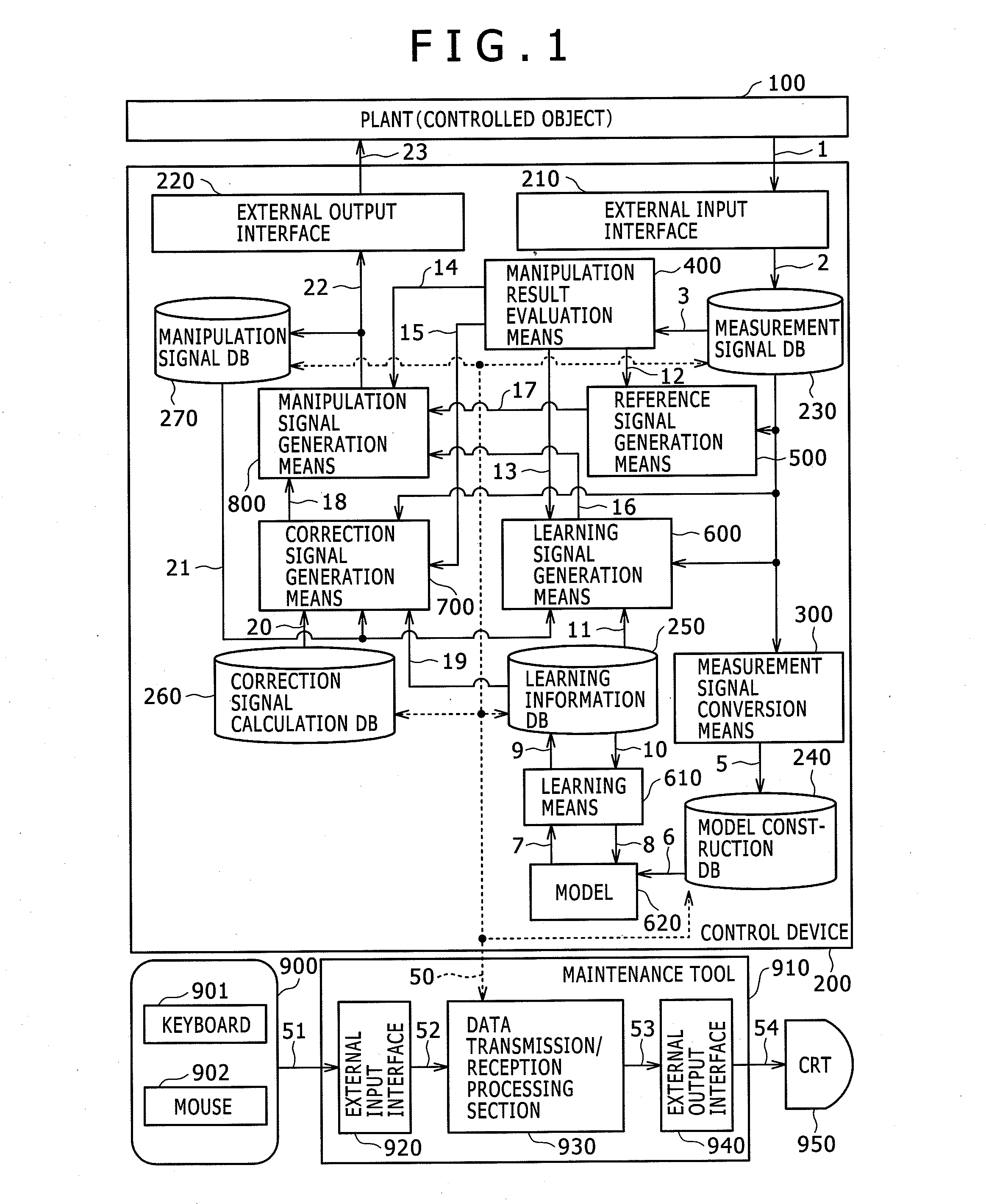
[0062]FIG. 1 is a control block diagram showing an overall configuration of a control device for a plant as a first embodiment of the invention.

[0063]In FIG. 1, in the present embodiment, a plant 100 is controlled by a control device 200.

[0064]The control device 200 has a configuration provided with measurement signal conversion means 300, manipulation result evaluation means 400, reference signal generation means 500, learning signal generation means 600, learning means 610, a model 620, correction signal generation means 700 and manipulation signal generation means 800 as operational equipment.

[0065]Further, the control device 200 is provided with a measurement signal database 230, a model construction database 240, a learning information database 250, a correction signal calculation database 260, and a manipulation signal database 270 as databases.

[0066]Further, the control device 200 has an external input interface 210 and an external output interface 220 as interfaces with the ...

second embodiment

[0185]Then, a control device for a thermal power plant as a second embodiment of the present invention will be explained with reference to the accompanying drawings.

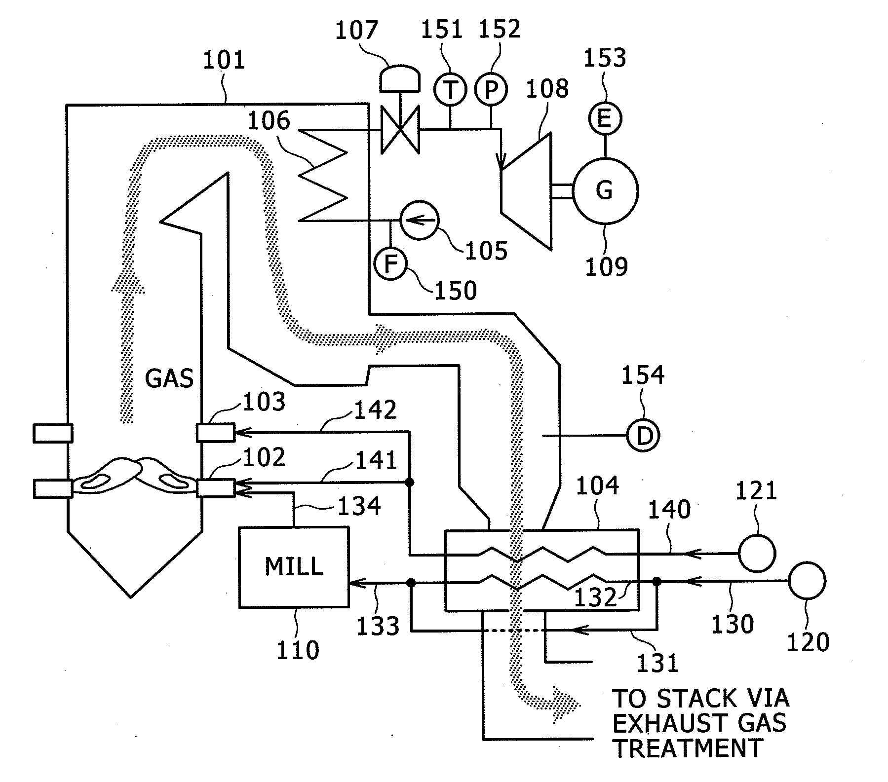
[0186]FIG. 7 is a control block diagram showing an overall configuration of a control device for a thermal power plant as a second embodiment of the invention.

[0187]Further, FIGS. 8A and 8B described later show a schematic configuration of a thermal power plant equipped with a boiler using coal as the fuel as a thermal power plant to be the controlled object of the control device for a thermal power plant as the second embodiment of the present invention shown in FIG. 7.

[0188]Since the control device for a thermal power plant as the second embodiment shown in FIG. 7 has a basic configuration common to the control device for a plant as the first embodiment shown in FIG. 1, the explanation for the constituents common thereto will be omitted, and only the constitutions different therefrom will hereinafter be explained.

[0189...

third embodiment

[0293]A gas concentration estimation device of another embodiment is directed to a coal-burning boiler provided to a thermal power plant, and a gas concentration estimation device adapted to perform an estimation process of the gas concentrations of CO and NOx included in an exhaust gas emitted from the coal-burning boiler using a neural network.

[0294]Regarding the materials of CO and NOx included in the exhaust gas emitted from the coal-burning boiler, there are provided limit values in the concentration in the exhaust gas based on the environmental restriction.

[0295]The gas concentration estimation device of a coal-burning boiler as the present embodiment is for estimating the concentration of CO and the concentration of NOx in the exhaust gas with respect to various operation conditions of the thermal power plant equipped with a coal-burning boiler.

[0296]A control system of a thermal power plant equipped with the coal-burning boiler of the present embodiment is for satisfying the...


PUM


Abstract

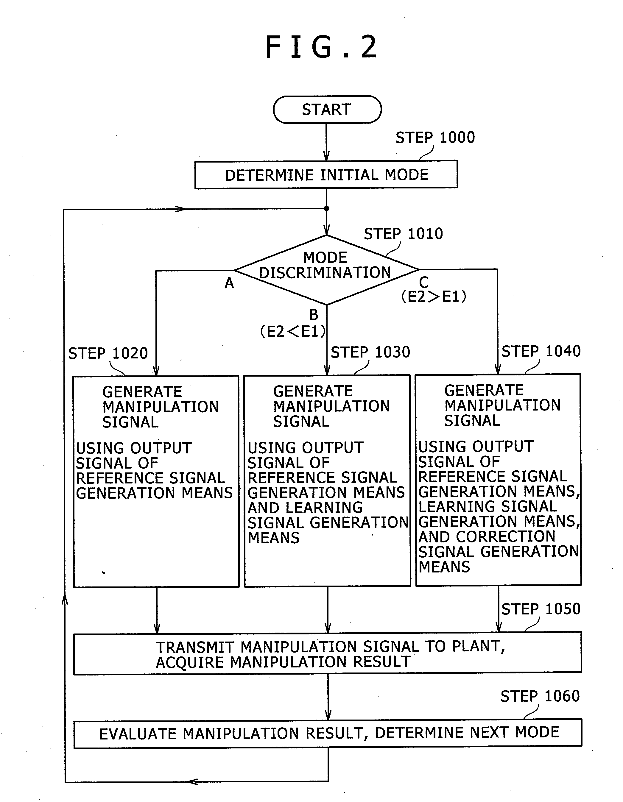
A control device for a plant includes a manipulation signal generation section for generating the manipulation signal to the plant, a model adapted to simulate a characteristic of the plant, a learning section for generating an input signal of the model so that an output signal obtained by the model simulating the characteristic of the plant satisfies a predetermined target, a learning signal generation section for calculating a learning signal in accordance with a learning result in the learning section, a manipulation result evaluation section for calculating a first deviation as a deviation between a first measurement signal of the plant obtained as a result of application of a certain manipulation signal to the plant and a target value of the measurement signal, and a second deviation as a deviation between a second measurement signal of the plant obtained as a result of application of an updated manipulation signal to the plant and the target value, and a correction signal generation section for generating, when the second deviation calculated by the manipulation result evaluation section is greater than the first deviation, a correction signal of the manipulation signal to be generated by the manipulation signal generation section.

Description

BACKGROUND OF THE INVENTION[0001]1. Field of the Invention[0002]The present invention relates to a control device for a plant, and a control device for a thermal power plant adapted to control a thermal power plant equipped with a boiler.[0003]Further, the present invention relates to a gas concentration estimation device and a gas concentration estimation method of a coal-burning boiler provided to the thermal power plant, and in particular to a gas concentration estimation device and a gas concentration estimation method of a coal-burning boiler adapted to estimate the concentrations of CO and NOx as gas components included in the exhaust gas emitted from the coal-burning boiler.[0004]2. Description of the Related Art[0005]In general, a control device for controlling a plant processes a measurement signal obtained from the plant as a controlled object, and calculates a manipulation signal to be applied to the controlled object to output as a control signal.[0006]The control device...

Claims


Application Information

Patent Timeline
IPC IPC(8): G06G7/48G05B13/02G06G7/63G05B15/02
CPCG05B13/027
Inventor SEKIAI, TAKAAKIYAMADA, AKIHIROEGUCHI, TORUSHIMIZU, SATORUFUKAI, MASAYUKIHAYASHI, YOSHIHARU
Owner HITACHI LTD
Learn More