Coating Apparatus

a coating apparatus and coating technology, applied in the direction of electrostatic spraying apparatus, coatings, instruments, etc., can solve the problem of coating fluid buildup

Active Publication Date: 2009-05-28
TOKUYAMA CORP
View PDF8 Cites 12 Cited by
  • Summary
  • Abstract
  • Description
  • Claims
  • Application Information

AI Technical Summary

Benefits of technology

[0018]In the above-described invention, it is preferred that the coating apparatus further comprising a waiting tank provided within a range of movement of the ejection nozzle of the primer coating device, wherein the waiting tank stores a solvent for preventing solidification of the primer coating fluid by dipping the ejection nozzle of the primer coating device in the solvent when the ejection nozzle is not in operation.

Problems solved by technology

In spin coating the lens with the photochromic coating fluid having high viscosity, moreover, the problem arises that even in the presence of centrifugal force during rotation, the coating fluid builds up at a peripheral edge portion of the lens, and drops onto the side surface of the lens.

Method used


Image

  • Coating Apparatus
  • Coating Apparatus
  • Coating Apparatus

Examples


Embodiment Construction

[0040]A coating apparatus according to the embodiment of the present invention will now be described with reference to the accompanying drawings.

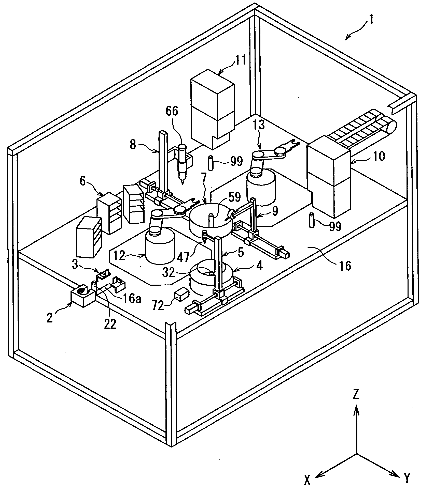
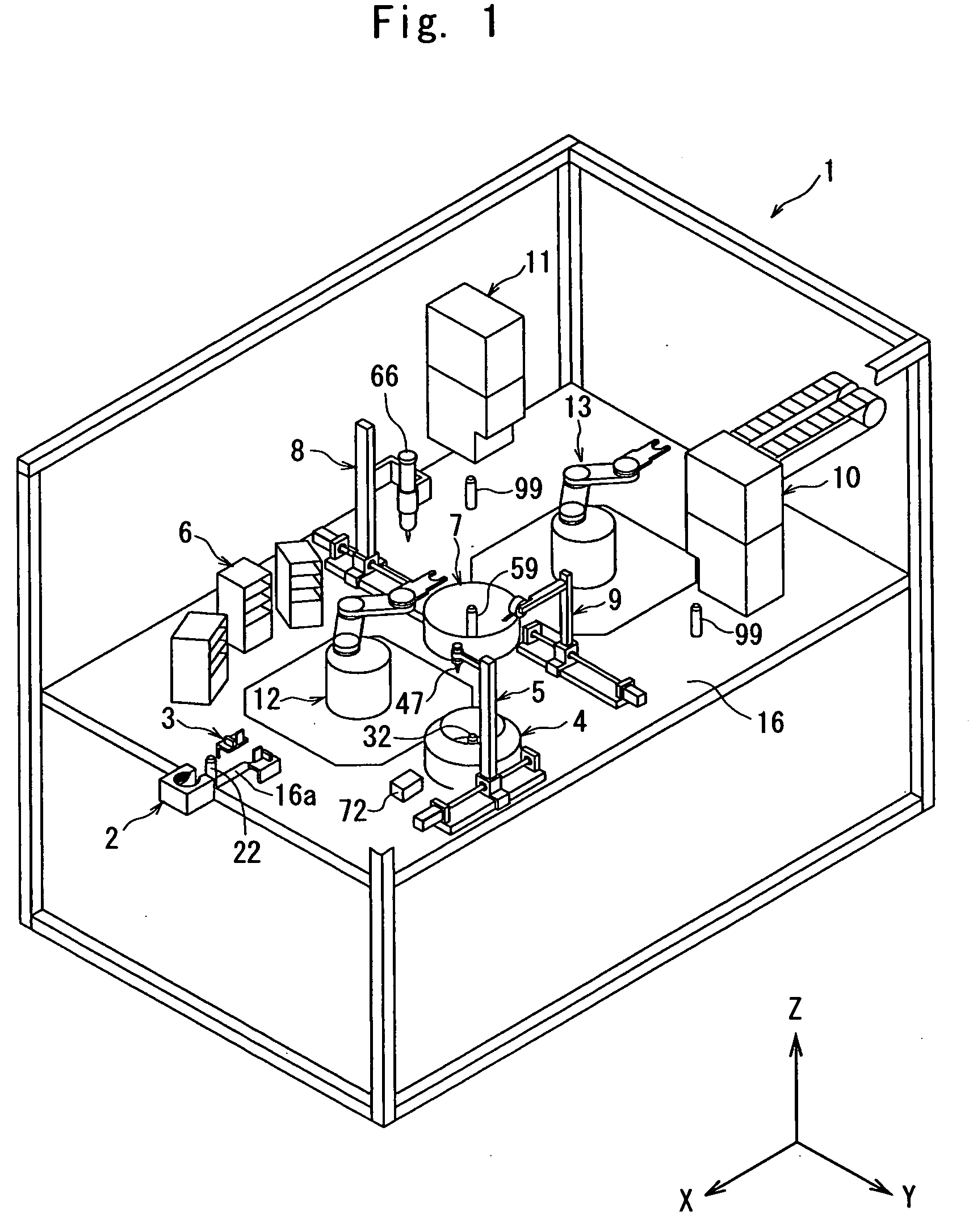
[0041]Herein, the description is presented, with the X-axis direction of the coating apparatus of FIG. 1 being the width direction of the coating apparatus, the Y-axis direction of the coating apparatus being the front-to-rear direction, and the Z-axis direction of the coating apparatus being the up-and-down direction.

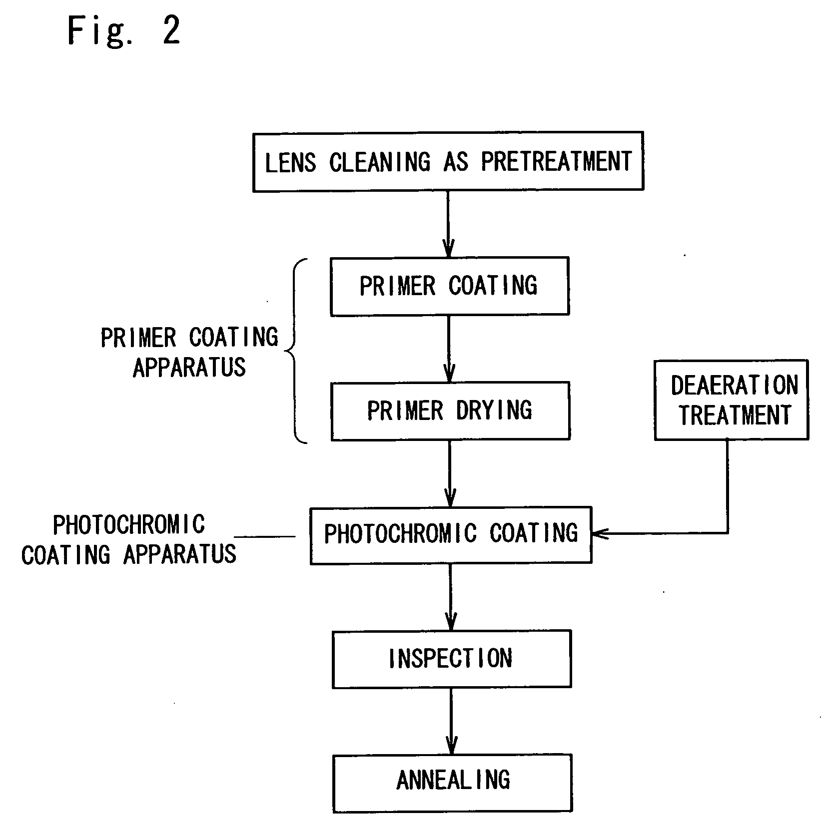
[0042]A coating apparatus 1 shown in FIG. 1 is an apparatus for forming a coating film on a lens. The apparatus for coating treatment is an apparatus for performing primer coating treatment (may hereinafter be referred to as primer coating) and photochromic coating treatment (may hereinafter be referred to as photochromic coating) in a photochromic coating process starting with lens cleaning as pretreatment and ending with annealing shown the flowchart of FIG. 2.

[0043]The coating apparatus 1 is equipped with a centering device...


PUM

PropertyMeasurementUnit
height measuringaaaaaaaaaa
rotational speedaaaaaaaaaa
photochromicaaaaaaaaaa

Abstract

The present invention provides a coating apparatus which can form a stable photochromic coating film. In the invention, a centering device, a lens height measuring device, a primer fluid applicator device, a primer spinning device, a drying device, a photochromic fluid applicator device, a photochromic spinning device, a UV device and a lens transport means comprising a pair of handling devices are provided to a coating apparatus. In the coating apparatus, it is possible to produce many photochromic lenses more efficiently by arranging devices and the lens transport means in such a manner that lens support portions of the centering device, the lens height measuring device, the primer spinning device, and the lens drying device are disposed inside the track of one handling device of the lens transport means, lens support portions of the UV device are disposed inside the track of the other handling device of the lens transport means, and the lens support portion of the photochromic spinning device is disposed inside both of the tracks.

Description

TECHNICAL FIELD[0001]This invention relates to a coating apparatus which can perform, for example, high quality photochromic coating of a lens for spectacles, etc.BACKGROUND ART[0002]Among materials which change in color when exposed to light is a photochromic substance. The photochromic substance has the property that its structure reversibly changes according to the presence or absence of ultraviolet radiation to change in absorption spectrum. This property results from the nature that when an isomer is irradiated with light of a particular wavelength, the single chemical substance, under the action of light, reversibly produces an isomer having a different absorption spectrum. The resulting different isomer is restored to the color of the original isomer by heat or light of a different wavelength.[0003]Photochromic spectacles utilize the above nature of the photochromic material for lenses. In an outdoor environment exposed to light including ultraviolet radiation, such as sunlig...

Claims


Application Information

Patent Timeline
Patent Type & Authority Applications(United States)
IPC IPC(8): B05C11/00
CPCB05B13/0221B05C11/08G02B5/23B29D11/00865B05D1/005
Inventor TAKAHASHI, NAOTOKOHNO, ATSUYUKIYAMAMOTO, SHUHEI
Owner TOKUYAMA CORP
Why Eureka
Try Eureka