Electric impact tightening tool

a technology of electric impact and torque, which is applied in the direction of manufacturing tools, mechanical energy handling, portable power-driven tools, etc., can solve the problems of large torsional force acting on the output shaft, failure of transmission of force, and above-described conventional electric impact torque tightening tools, etc., to achieve low reaction force and durability, small size and weight

Inactive Publication Date: 2009-05-28
YOKOTA IND
View PDF10 Cites 30 Cited by
  • Summary
  • Abstract
  • Description
  • Claims
  • Application Information

AI Technical Summary

Benefits of technology

[0012]It is therefore an object of the present invention to provide an electric impact tightening tool that is small in size and light in weight, has a low reaction force and durability.
[0014]The electric impact tightening tool according to the present invention can be small in size and in weight, and has a low reaction force and durability.

Problems solved by technology

However, the above-described conventional electric impact tightening tool has problems as described below.
Each time a high torque is generated, therefore, such decrease causes a large torsional force to act on the output shaft of the electric motor which would rotate at a constant speed.
As a result, the output shaft s and the rotor r or the press-fitted part of the socket k failed to slide on each other properly and resulting in failure of the transmission of the force.
In case of a brush type motor, the proper positional relation between a commutator and a rotor is lost, and this electric motor ceases to work properly in a short time or does not work any more.
Therefore, a relatively large speed reducer becomes necessary and consequently the electric impact tightening tool increases in weight by the weight of the speed reducer.
Therefore, a worker receives the power transmitted to the case and feels it as a relatively large reaction force, which results in deteriorating workability and increasing the degree of the worker's fatigue, and then the worker cannot work using the electric tightening tool for long hours.

Method used


Image

  • Electric impact tightening tool
  • Electric impact tightening tool
  • Electric impact tightening tool

Examples


embodiment 1

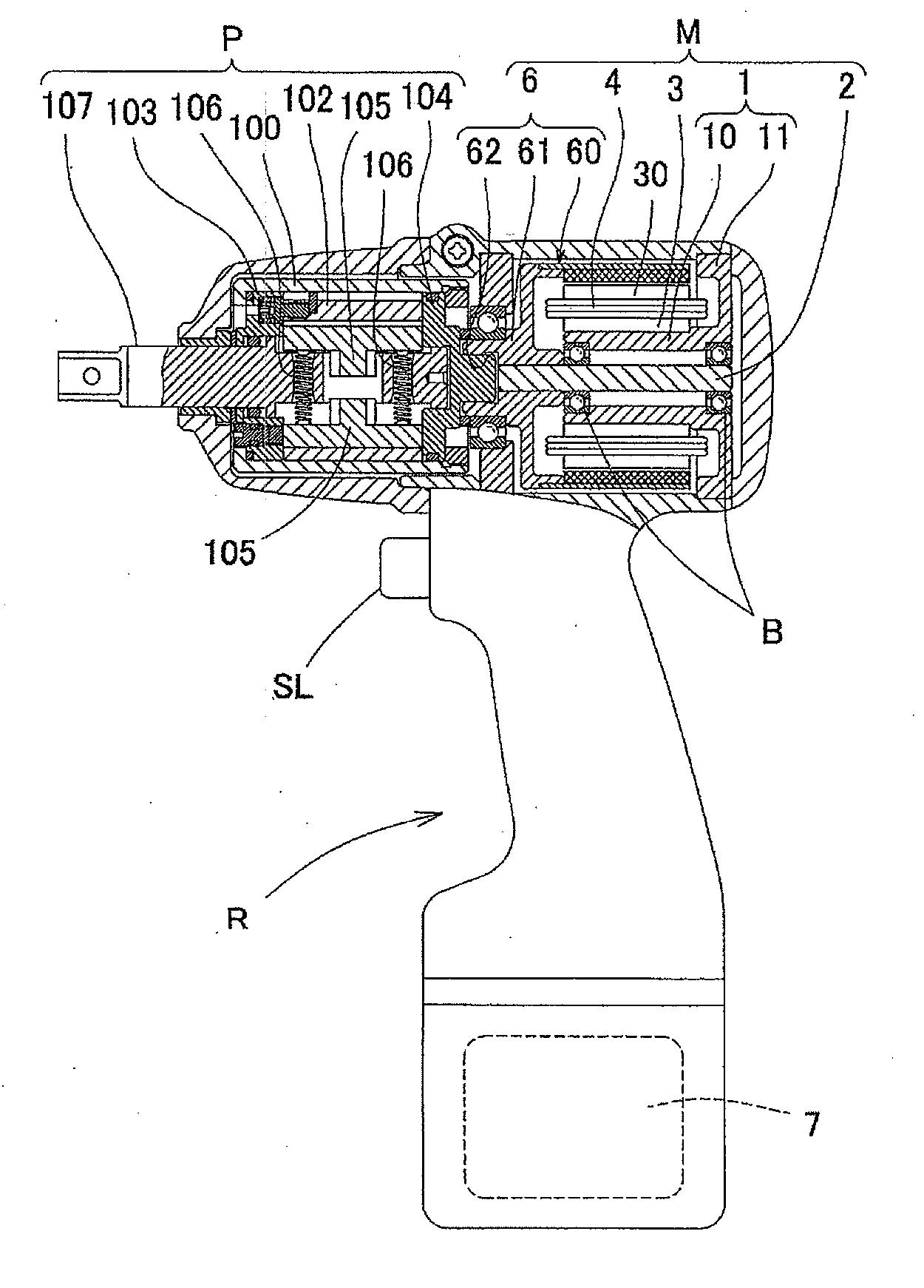
[0039]Embodiment 1 relates to an electric impulse wrench R, one kind of the electric impact tightening tool of the present invention.

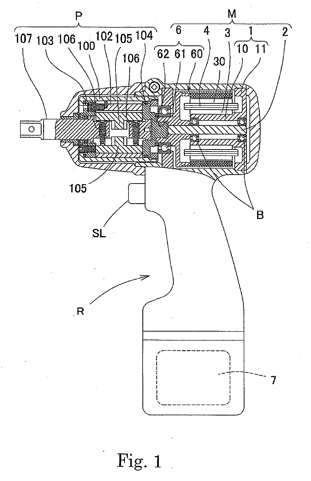
[0040]This electric impulse wrench R directly transmits the rotation of a rotor 6, which is an output section of an outer-rotor electric motor M, as shown in FIG. 1, to a liner 102 of a hydraulic pulse generation section P (corresponding to the impact generation section described in the section of Summary of the Invention), and, by an impact pulse generated in the hydraulic pulse generation section P, generates a strong torque on a main shaft 107. And the outer-rotor electric motor M is driven to rotate with a battery power supply 7.

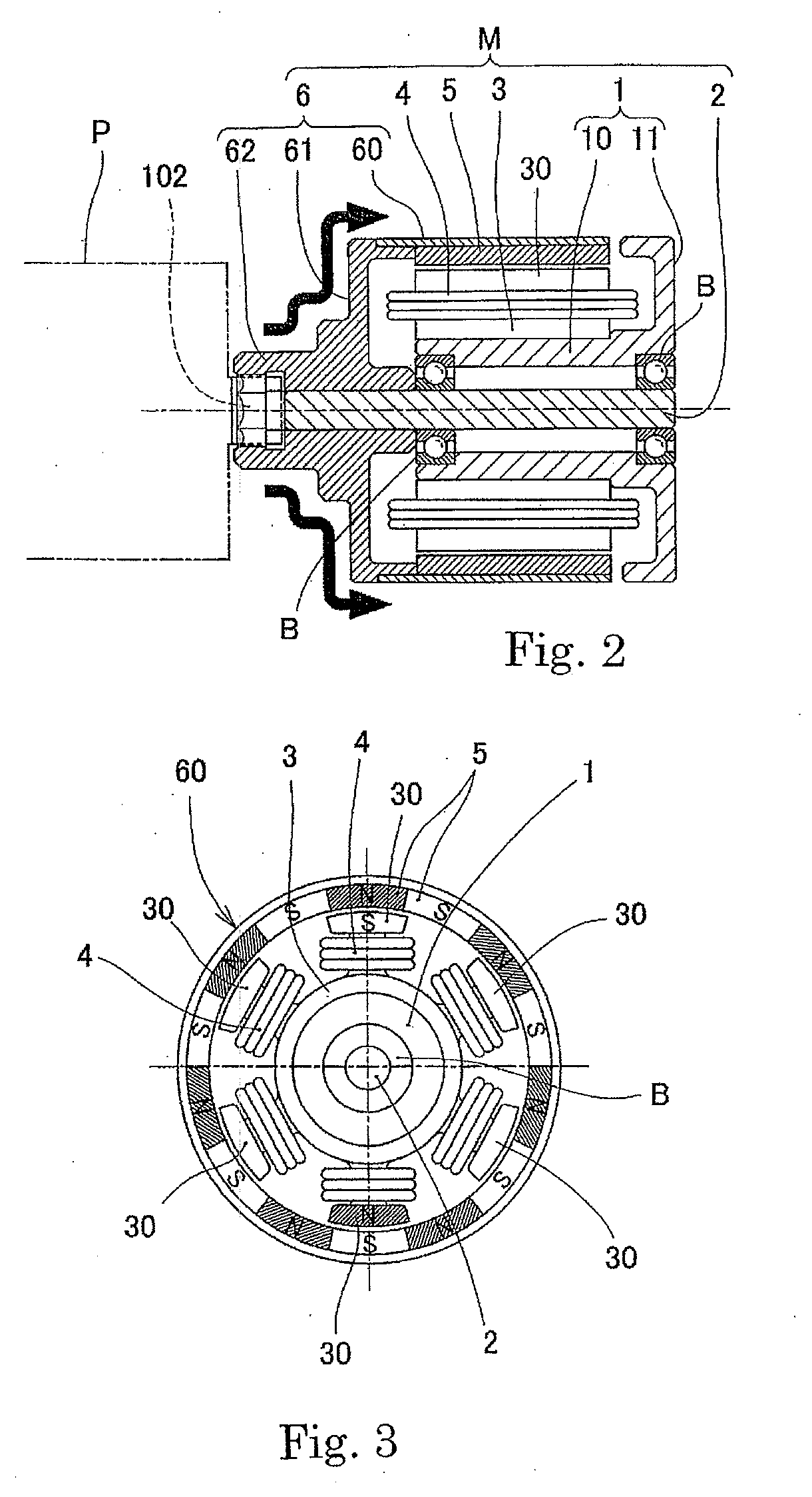
[0041]As shown in FIGS. 1 to 3, the outer-rotor electric motor M includes a support 1, a rotary shaft 2, stators 3, coils 4, magnets 5 and a rotor: the support 1 has a cylindrical portion 10 and a flanged portion 11 provided on a side of one end of the cylindrical portion; the rotary shaft 2 is provided via inner races of a...

embodiment 2

[0079]Embodiment 2 relates to an electric hammer wrench R1, one kind of the electric impact tightening tool of the present invention, having a hammer type impact mechanism 8 (corresponding to the impact generation section described in the section of Summary of the Invention).

[0080]As shown in FIG. 17, this electric hammer wrench R1 has a hammer impact mechanism 8 including a hammer 80 and an anvil 81. When the hammer 80 rotates in response to the rotation of an outer-rotor electric motor M and gives an impacting blow to the anvil 81, an impact force is generated in the anvil 81. The impact force is transmitted to a bolt and the like as torque, and they are tightened. An impact force is generated once per revolution of the hammer 8.

[0081]This electric hammer wrench R1 also employs an outer-rotor electric motor M like in Embodiment 1 and, therefore, apparently advantageously functions likewise.

embodiment 3

[0082]Embodiment 3 relates to an electric clutch wrench R2, one kind of the electric impact tightening tool of the present invention, having a clutch type impact generation section 9 (corresponding to the impact generation section described in the section of Summary of the Invention).

[0083]As shown in FIG. 18, this electric clutch wrench R2 has a clutch type impact generation section 9 provided with a clutch section 90 having a lower clutch 90a and an upper clutch 90b engaging therewith, a main shaft 91, and a coil spring 92 that forces to push the upper clutch 90b toward the lower clutch 90a. The rotational force of an outer-rotor electric motor M is transmitted to the main shaft 91 via the clutch section 90 as tightening torque.

[0084]In the clutch type impact generation section 9 in this electric clutch wrench R2, engaging part 93 between the lower clutch 90a and the upper clutch 90b is in the manner that respective tapered clutches engage each other. When a bolt and the like are ...


PUM


Abstract

An electric impact tightening tool in which the rotation of an output section of an electric motor is transmitted to an impact generation section (P) and impact force generated in the impact generation section (P) causes a main shaft (107) to produce strong torque, where the electric motor is an outer rotor electric motor (M). The outer rotor electric motor (M) has low-speed, high-torque characteristics. In the tool, the impact generation section (P) and a rotor flange (61) at the forward end of the motor (M) are adapted to rotate integrally. The electric impact tightening tool is small sized and lightweight, produces low reaction force, and has durability.

Description

TECHNICAL FIELD[0001]The present invention relates to an electric impact tightening tool.BACKGROUND ART[0002]In a conventional electric impact tightening tool, as disclosed, for example, in Japanese Patent Laid-Open No. 5-123975, the rotation of an output shaft of an inner-rotor electric motor is usually transmitted to an impact generation section via a reducer and an impact force generated in the impact generation section causes a strong torque on a main shaft.[0003]However, the above-described conventional electric impact tightening tool has problems as described below.(Problem 1)[0004]In an inner-rotor electric motor, as shown in FIG. 20, torque is transmitted from a magnet g to a rotor r and then a thin and brittle output shaft s which is press fitted into the rotor, and further to an impact generation section through a socket k provided at a forward end of the output shaft s.[0005]The rotation speed of the impact generation section decreases at a stroke due to generation of a h...

Claims


Application Information

Patent Timeline
Patent Type & Authority Applications(United States)
IPC IPC(8): B25B21/02H02K7/14H02K21/22
CPCB25B21/02B25F5/006B25B21/00
Inventor MIZUHARA, MASARU
Owner YOKOTA IND
Why Eureka
Try Eureka