Panel-type input device and electronic apparatus having the same

Inactive Publication Date: 2009-05-28
FUJITSU COMPONENENT LTD
View PDF6 Cites 23 Cited by
  • Summary
  • Abstract
  • Description
  • Claims
  • Application Information

AI Technical Summary

Benefits of technology

[0011]It is an object of the present invention to provide a panel-type input device having a resistive-type configuration, which can reduce an operati

Problems solved by technology

In a configuration where the upper-side electrode plate of the conventional resistive-type touch panel is formed from a resinous film substrate and an ITO coat, if an input operation is performed in an outer peripheral portion of the input-permissible area, adjoining the frame area, the upper electrode plate tends to be locally bent along the inner edge of the intermediate layer, which causes excessive stress in the ITO coat, and it is thus concerned that the ITO coat may be damaged by repeating the input operation and coordinate input precision (i.e., pressing-point detection precision) may be degraded.
When using such a frame-shaped attaching member, the input operation to t

Method used


Image

  • Panel-type input device and electronic apparatus having the same
  • Panel-type input device and electronic apparatus having the same
  • Panel-type input device and electronic apparatus having the same

Examples


first embodiment

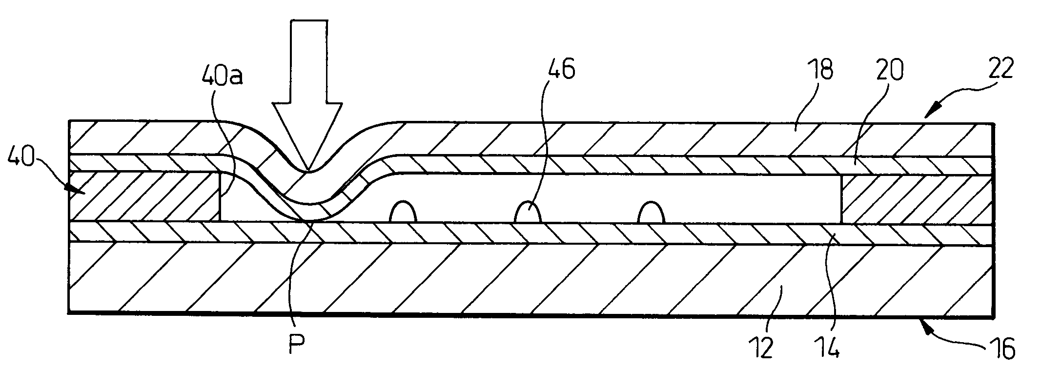
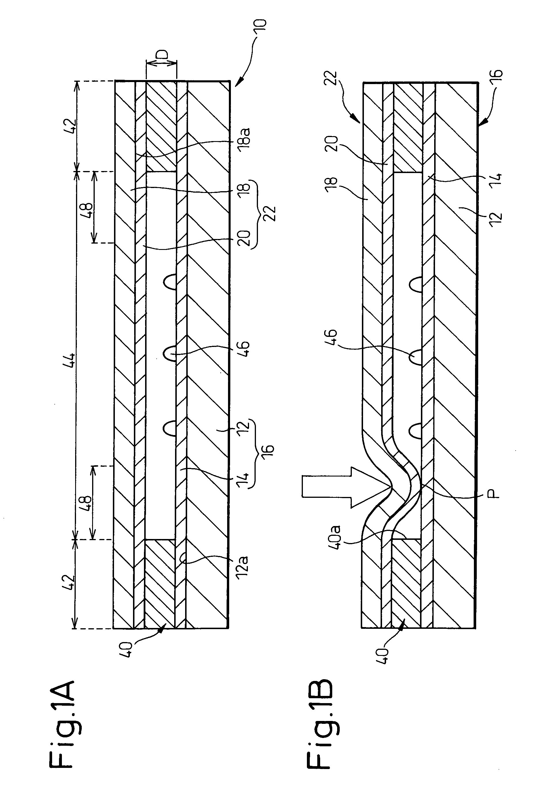
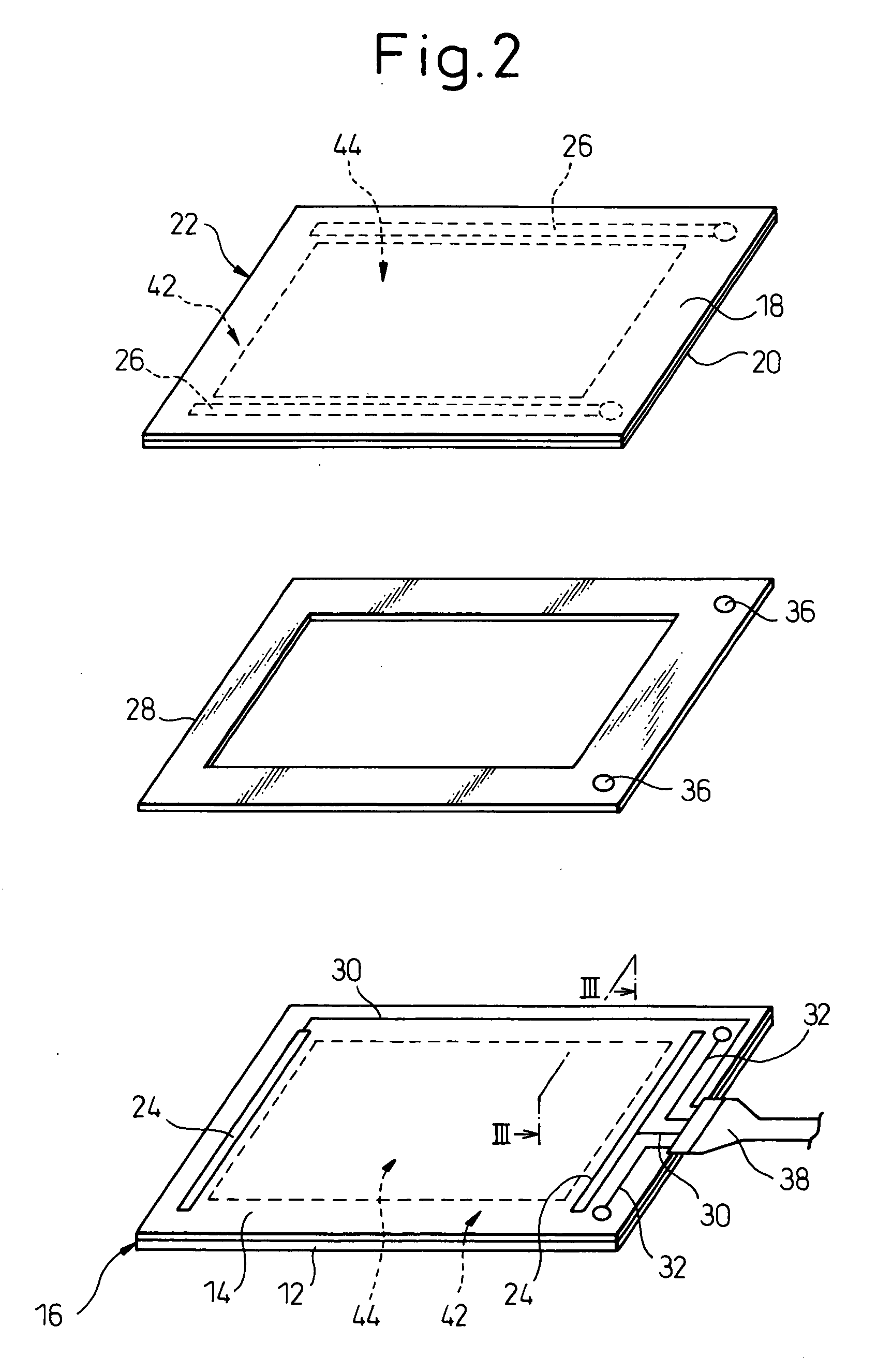
[0038]Referring to the drawings, FIGS. 1A and 1B show, in schematic sectional views, essential components of a panel-type input device 10 according to the present invention in non-operated and operated states, FIG. 2 shows, in an exploded schematic perspective view, the essential components of the panel-type input device 10, and FIG. 3 shows, in an enlarged sectional view, a part of the panel-type input device 10.

[0039]The panel-type input device 10 includes a first electrode plate 16 having a first electrical-insulating substrate 12 and a first electrical-conductive coat 14 provided on a surface 12a of the first substrate 12, a second electrode plate 22 having a second electrical-insulating substrate 18 and a second electrical-conductive coat 20 provided on a surface 18a of the second substrate 18 (FIG. 1A). The first substrate 12 and first conductive coat 14 of the first electrode plate 16 and the second substrate 18 and second conductive coat 20 of the second electrode plate 22 h...

experiment 1

[0056][Experiment 1]

[0057]A sample simulating the panel-type input device 10 was prepared in such a manner that a pair of ridges T were formed on the upper surface of a substrate S so as to be spaced from and parallel to each other (150 μm height, 30 mm spacing), and that a second electrode plate 22 configured by providing a second conductive coat 20 made of a polythiophene-based conducting polymer (160 nm thickness) to coat a second substrate 18 (188 μm thickness) formed from a PET film was securely placed on the top faces of the ridges T in a state where the second conductive coat 20 was opposed to the substrate S and second electrodes 26 were situated outside of the ridges T (FIGS. 4A and 4B). For this sample, a pen U having a hemispherical tip with 0.8 mm radius (made of polyacetal (POM)) was used, and the pen tip was moved and slid in a reciprocal motion (10,000 times) at a predetermined position on the outer surface 18b of the second substrate 18 of the second electrode plate ...

experiment 2

[0061][Experiment 2]

[0062]The height of each ridge in the aforementioned sample was modified to 250 μm, and an experiment was performed to the modified sample and the comparative examples, the steps of which were generally identical to those of the experiment 1. Result of the experiment is shown in FIG. 6 (a vertical axis indicates the rate of change Δ in the resistance value R relative to an initial value).

[0063]As will be understood from FIG. 6, even in the second electrode plate 22 including the second conductive coat 20 made of a conducting polymer, increase in the resistance value R was observed after the pen tip was slid in a reciprocal motion at a position spaced about 0.25 mm from the ridge T. Therefore, it is desirable, for ensuring operational reliability over a long period, that the panel-type input device 10 by way of example is configured such that the thickness of the intermediate layer is less than 250 μm. Even if the thickness of the intermediate layer is about 250 μ...


PUM


Abstract

A panel-type input device including a first electrode plate, a second electrode plate and an intermediate layer fixing the first electrode plate to the second electrode plate. The first electrode plate includes a first substrate and a first conductive coat on the first substrate. The second electrode plate includes a second substrate and a second conductive coat on the second substrate, the second conductive coat being formed by using a conducting polymer. The intermediate layer is provided along outer edges of mutually opposed first and second conductive coats and ensures a spacing distance therebetween. The first and second electrode plates have a frame area including a region in which the intermediate layer is provided, and an input-permissible area surrounded by the frame area. When the panel-type input device is attached to an object with the first electrode plate being laid on the object, the second electrode plate is disposed in such a manner that an outer peripheral portion of the input-permissible area, adjoining the frame area, is exposed so as to permit an input operation.

Description

BACKGROUND OF THE INVENTION[0001]1. Field of the Invention[0002]The present invention relates to a panel-type input device. The present invention also relates to an electronic apparatus including a panel-type input device.[0003]2. Description of the Related Art[0004]A panel-type input device has been known as an input device of an electronic apparatus including a display unit, such as a personal computer, a personal digital assistant (PDA), an automatic teller machine (ATM), etc., which is operated to indicate two-dimensional coordinate data in the display unit by an operator pressing a desired point on a panel surface with his finger or a pen. In particular, a panel-type input device with a transparent structure, which can be mounted on a screen of a display unit, such as a liquid crystal display (LCD), a plasma display panel (PDP), a cathode ray tube (CRT), etc., has been widely used as a touch panel, and in recent years, has been mounted on a portable terminal unit having a mobil...

Claims


Application Information

Patent Timeline
IPC IPC(8): G06F3/044
CPCG06F1/1626G06F1/1637G06F2203/04809G06F3/04886G06F3/045G06F3/0412
Inventor ENDO, MICHIKO
Owner FUJITSU COMPONENENT LTD
Why Eureka
Try Eureka