Stereo camera

a camera and stereo technology, applied in the field of stereo cameras, can solve the problems of deteriorating reliability in collision avoidance systems, affecting the accuracy of attachment, and relying on the error of measured distances, so as to improve the accuracy of attachmen

Inactive Publication Date: 2009-05-28
PANASONIC CORP
View PDF1 Cites 23 Cited by
  • Summary
  • Abstract
  • Description
  • Claims
  • Application Information

AI Technical Summary

Benefits of technology

[0015]According to this structure, it is possible to prevent from ...

Problems solved by technology

Generally, an error of a measured distance depends on the accurate disposition of two cameras on the both sides of a stereo camera.
When the position of the two cameras changes or the optical axis of ...

Method used


Image

  • Stereo camera
  • Stereo camera
  • Stereo camera

Examples


Embodiment Construction

[0031]Hereinafter, a stereo camera according to an embodiment of the invention will be described using the drawings.

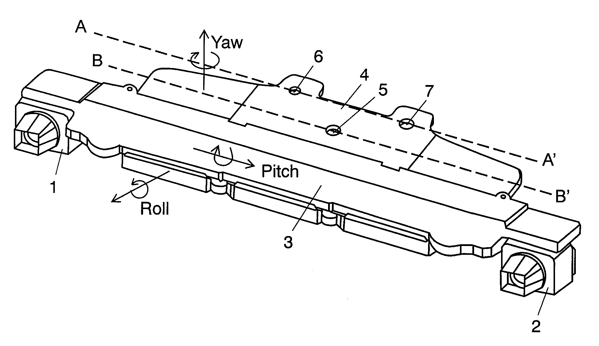
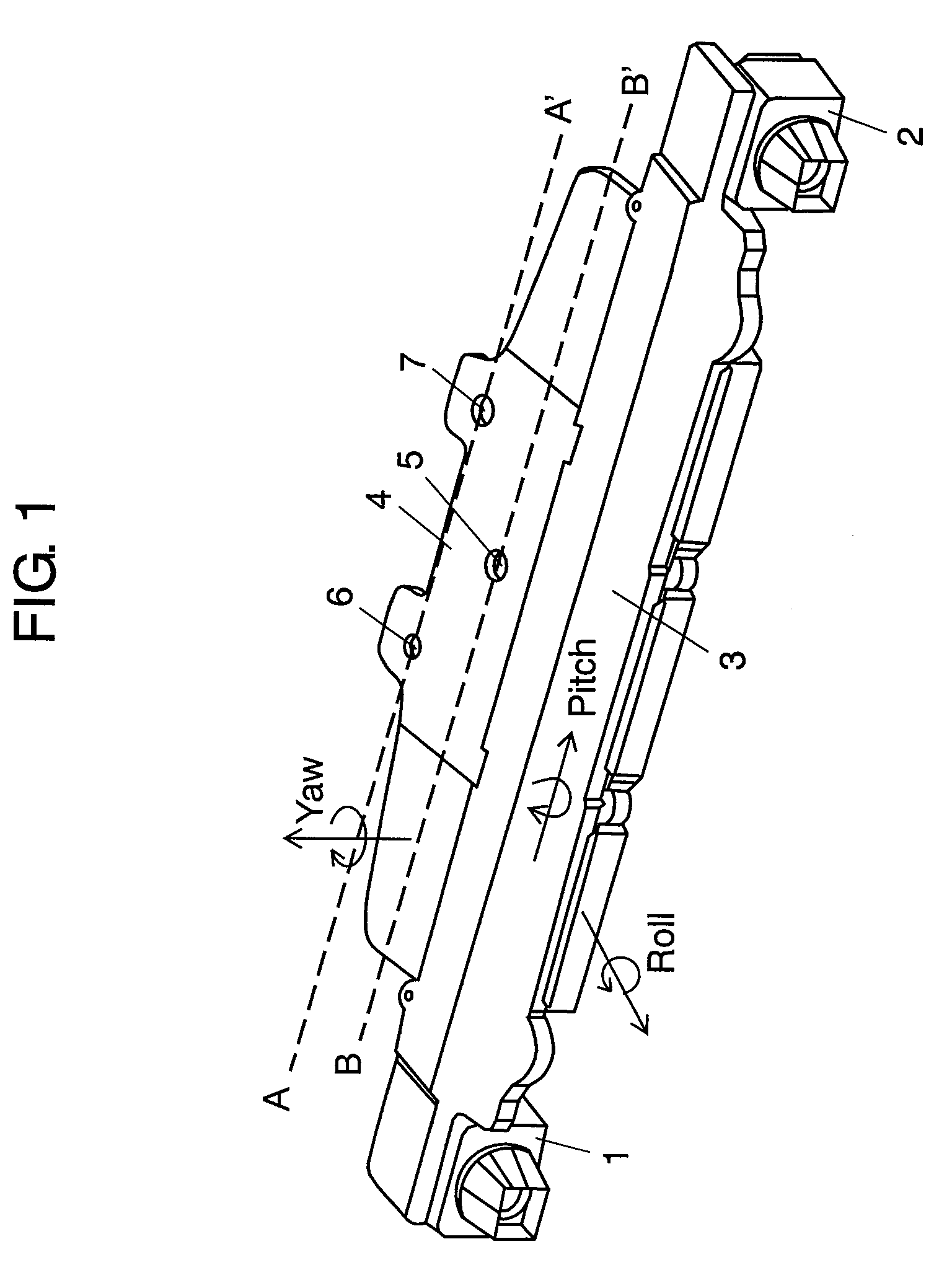
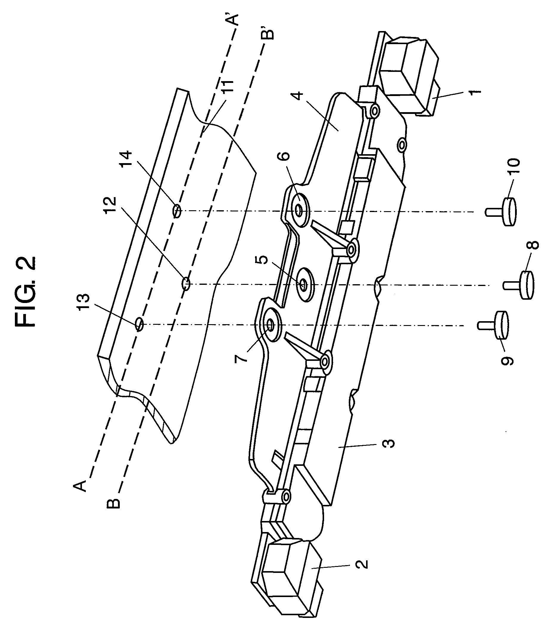
[0032]FIG. 1 is a perspective view of the stereo camera according to the embodiment of the invention. In FIG. 1, the stereo camera of the invention comprises right camera 1, left camera 2, camera stay 3 for holding right camera 1 and left camera 2 at predetermined positions, and attachment portion 4 having openings for fixing camera stay 3 to a vehicle. The centers of openings 5, 6, and 7 are positioned on a plurality of virtual lines (in FIG. 1, two dotted lines AA′ and BB′) parallel to the base line connecting right camera 1 and left camera 2. A plural number of openings (two in FIG. 1) are arranged on the virtual parallel line AA′ far away from camera stay 3 and one opening is arranged on the virtual parallel line BB′ closer to camera stay 3 than the faraway virtual parallel line AA′.

[0033]Camera stay 3 is a rectangular plate, having attachment portion 4 protruding ...


PUM


Abstract

It has a right camera, a left camera, a camera stay which holds the right camera and the left camera at predetermined positions, and an attachment portion having openings for fixing the camera stay to a vehicle, in which the openings are positioned at a plurality of virtual lines parallel to a base line connecting the right camera and the left camera, a plurality of the openings are arranged on a virtual parallel line far from the camera stay, and one opening is arranged on a virtual parallel line closer to the camera stay than the faraway virtual parallel line. This structure provides a stereo camera which can prevent from deformation of the camera stay owing to a difference of expansion between the attachment portion and the camera stay and from deviation in the base length and the optical axis of the both cameras, with high distance-measurement accuracy even in a change of surrounding temperature.

Description

TECHNICAL FIELD[0001]The invention relates to a stereo camera which estimates a distance to a preceding object while processing an azimuth difference of the two images taken by right and left cameras.BACKGROUND ART[0002]There is known a stereo camera which estimates a distance from a vehicle to a preceding object while processing the azimuth difference of the two images taken by the right and left cameras that are arranged in the front portion of the vehicle with the optical axes set apart at a predetermined distance (base length). This stereo camera is mounted on a vehicle as a distance measuring system for measuring a distance to a target and used as a collision avoidance system for warning of a distance between two vehicles and warning of an obstacle.[0003]FIG. 7 is a perspective view of the conventional stereo camera. In FIG. 7, the conventional stereo camera has right camera 21, left camera 22, camera stay 23 which holds right camera 21 and left camera 22 at predetermined posit...

Claims


Application Information

Patent Timeline
IPC IPC(8): H04N13/00
CPCG01C3/18G03B35/08G01S11/12G03B17/56
Inventor UCHIYAMA, HIROOINAGAKI, TATSUHIKOMATSUSHIMA, YUKIHIRO
Owner PANASONIC CORP
Why Eureka
Try Eureka