Image processing of medical images

a medical image and image processing technology, applied in the field of medical imaging, can solve the problems of difficulty in seeing variations or differences, two images will lose resolution, and the fusion is not done yet for images, so as to achieve good contrast and improve contrast

Inactive Publication Date: 2009-05-28
BARCO NV
View PDF12 Cites 51 Cited by
  • Summary
  • Abstract
  • Description
  • Claims
  • Application Information

AI Technical Summary

Benefits of technology

[0007]It is an object of the present invention to provide good methods and systems for processing medical images. It is an advantage of embodiments according to the present invention that methods and systems for fusing image information are provided, thus visualising image information of a plurality of medical images. It is an advantage of embodiments according to the present invention that methods and system are provided resulting in images with higher contrast, e.g. by mapping information directly to coordinates corresponding with sensitive components of the human vision system. Furthermore, it is an advantage of embodiments according to the present invention that the fusion and / or mapping processing provided corresponds to the way of how the human visual system (HVS) decomposes the image in the brain in an opponent colour space, the methods and systems thus mimicking the human vision system. Methods and systems according to embodiments of the present invention thus have the advantage to modify the data to have a good, optionally the best possible, response from the human eye.

Problems solved by technology

Placing different medical images aside each other to evaluate objects often results in inaccuracy as it can be difficult to see variations or differences in images that are not in overlay e.g. due to inaccuracy of localizing a feature in different images of the same object.
As far as known, such fusion is not done yet for images recorded with the same technique, e.g. time evolution of an object on CT images.
The downside of the above combination scheme therefore is that the two images will lose resolution.
The latter results in a loss of grayscale resolution, a low contrast and a low luminance.
Furthermore, fusion of PET and CT images involves a large number of controls and changing of the fusion parameter asks for adoption of the window leveling.
The last one has the disadvantage of reducing the spatial resolution, whereas, as described above, the overlay solution has the disadvantage of reducing the contrast and luminance of the images.

Method used


Image

  • Image processing of medical images
  • Image processing of medical images
  • Image processing of medical images

Examples


example 1

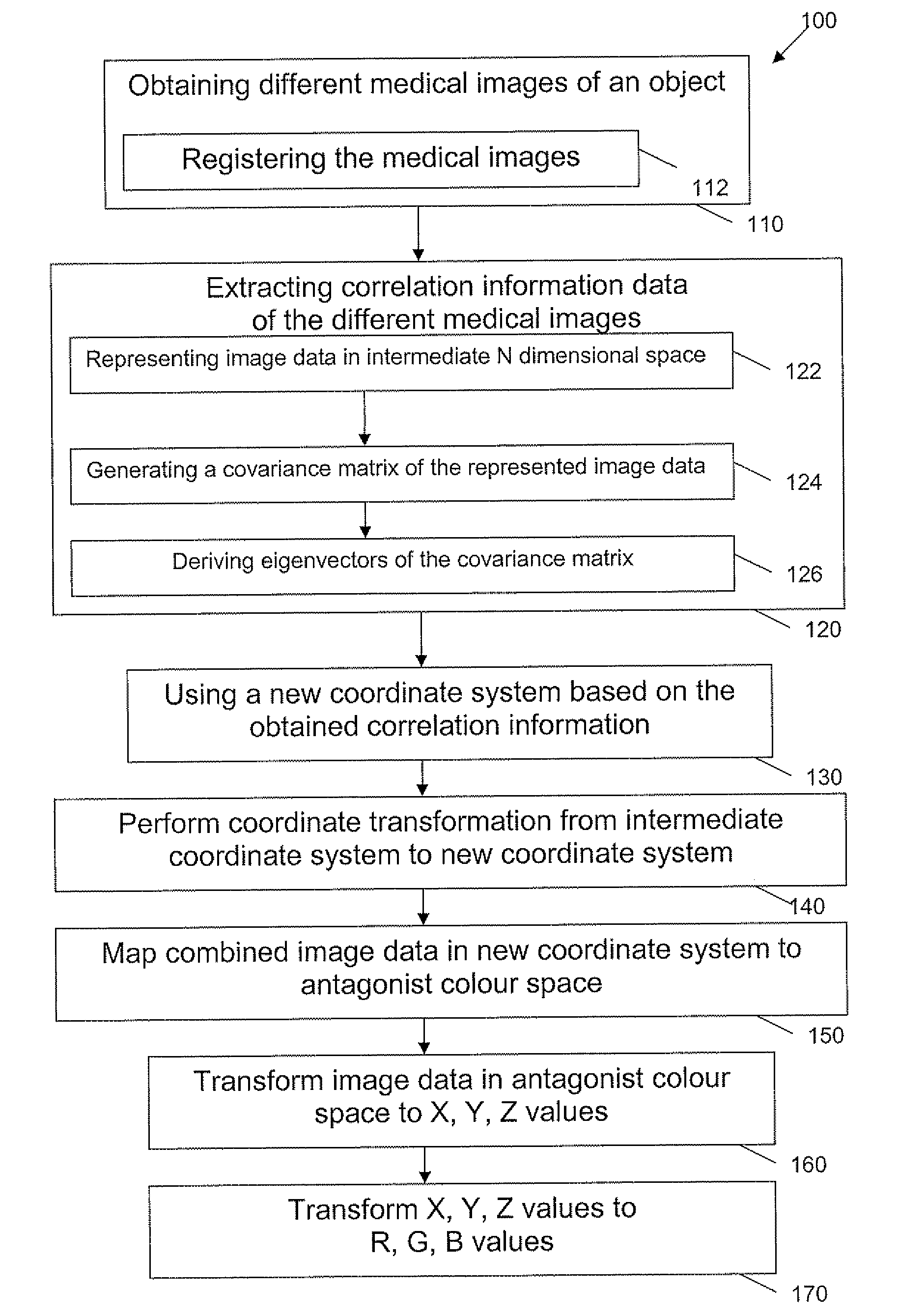
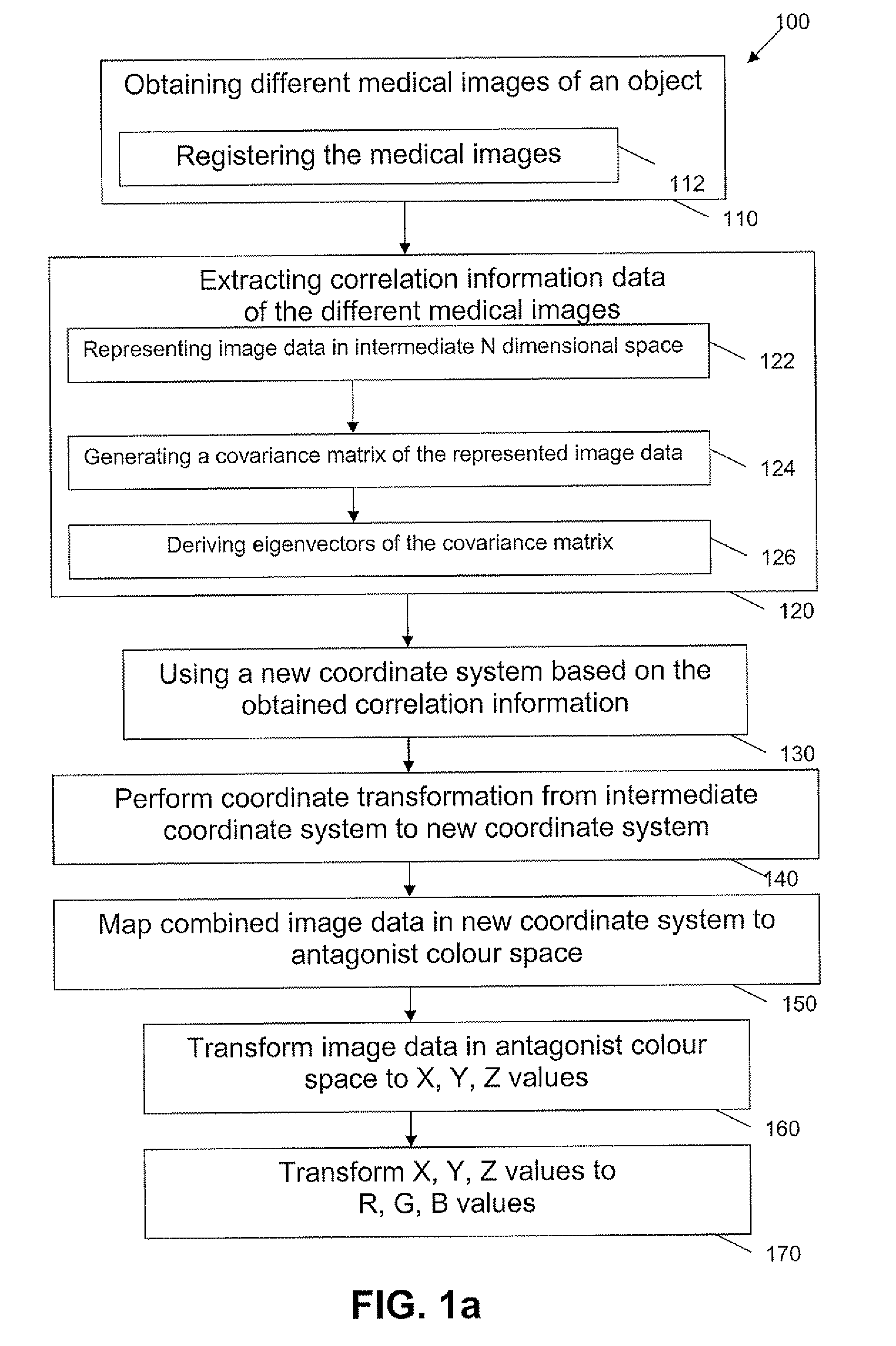
[0088]In a first example, fusion of a plurality of computed tomography images is described. In the present example the relation between the different images is time, i.e. images of the same object are taken at different moments in time. By way of example, a multiple phase CT-CT study is used to illustrate the possibilities of useful combining, i.e. fusing of images. In this example, a first CT scan is made without the use of contrast fluid, a second scan is taken whereby the patient was injected with contrast fluid, a third and fourth scan further show the fade out of the effect of the contrast fluid over time. The present example illustrates that contrast fluid may help the blood to absorb more of the X-ray radiation and in this way make the blood flow more visible in the CT image. Although two images are made under different circumstances and on different times, they remain highly correlated.

[0089]In the present example, the data analysis is performed using principal component ana...

example 2

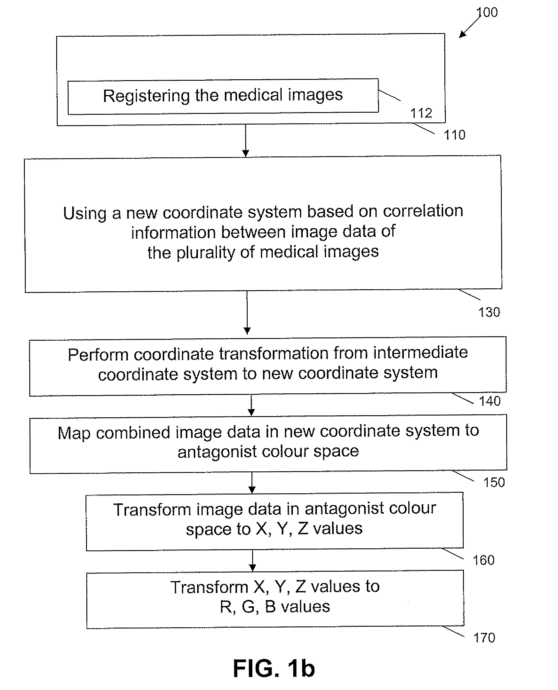
[0095]A second example provides a more detailed illustration of the optional step of mapping information to an antagonist colour space. The present example illustrates the fusion of a CT image and a PET image. In this example, mapping to the antagonist colour space L*, a*, b* is described. The CT image thereby is mapped on the luminance axis L*, whereas the PET image uses both the red-green component axis, a*, and the yellow-blue axis, b*, to map its data points according to a certain colour map. The latter illustrates that for images that do not correlate significantly enough for performing principal component analysis, the images can be assigned to a specific channel in the antagonist colour space.

[0096]As in other imaging applications a level and width of the CT image can be controlled. For the PET image a blend function was used that controls the width and the level of the PET image and the level influences the luminance. Although it was mentioned above that PET is mapped on a* ...

example 3

[0104]A third example illustrates the example wherein there are multiple registered datasets that reflect an evolution over time, e.g. a three phase liver study and wherein a moving window technique is used. The new coordinate system thereby does not need to be based on PCA, but may be based thereon. In one example, the new coordinate system is based on visualisation of differences over time. For a three dimensional dataset DS(1), DS(2), DS(3), . . . a new coordinate system may be such that the new coordinate1 equals the original coordinate of the N'th dataset, the new coordinate2 equals the difference between the original coordinate1 of the N'th dataset and original coordinate1 of the N−1st dataset, new coordinate3 is an average of original coordinate of the Nth, the N−1st and N−2nd dataset minus the original coordinate of the N−3rd dataset. It is to be noticed that this technique also can be applied to a single dataset, e.g. a single CT dataset, whereby the “N medical images” are ...


PUM


Abstract

An image processing method and system are described for processing medical images. The method comprises using a new coordinate system for representing combined image data of said plurality of medical images based on correlation information between image data of a plurality of medical images. The method further may comprise extracting such correlation information, and after said representing, mapping obtained image data to an antagonist colour space, thus resulting in visualisation with a fused image with high contrast and luminance and with particular human vision parameters relating to equalities and differences in the plurality of medical images studied.

Description

FIELD OF THE INVENTION[0001]The present invention relates to the field of medical imaging. More particularly, the present invention relates to the field of image processing and visualisation of multiple medical data sets simultaneously, more particularly to methods and systems for fusing multiple medical data sets simultaneously.BACKGROUND OF THE INVENTION[0002]In order to positively evolve to accurate medical diagnoses, at present often complementary information obtained from different sources are compared. For example positron emission tomography (PET) and computed tomography (CT) often are used in combination as they provide different information that hardly is correlated, resulting in additional useful information being present, e.g. for the radiologist, and thus resulting in a better overall picture of the subject under study. Alternatively or in addition thereto, comparison of different images obtained using the same technique, e.g. computed tomography, at different periods in...

Claims


Application Information

Patent Timeline
Patent Type & Authority Applications(United States)
IPC IPC(8): G06K9/00
CPCG06T5/50G06T7/0026G06T7/0034G06T2207/30004G06T2207/10104G06T2207/20221G06T2207/10081G06T7/32G06T7/35
Inventor KIMPE, TOMWOESTENBORGHS, WOUTERMARCHESSOUX, CEDRIC
Owner BARCO NV
Why Eureka
Try Eureka