Method for manufacturing polycrystalline silicon

Active Publication Date: 2009-05-28
HIGH-PURITY SILICON CORP
View PDF2 Cites 17 Cited by
  • Summary
  • Abstract
  • Description
  • Claims
  • Application Information

AI Technical Summary

Benefits of technology

[0019]According to the polycrystalline silicon manufacturing method of the present invention, by first rapidly increasing and then slowly increasing the ejection velocity of the raw material gas after the initial stabilizing step of the deposition, the raw material gas can be sufficiently spread up to the upper sides of the long silicon rods and accordingly a fresh raw material gas can be sufficiently supplied

Problems solved by technology

As a result, silicon is reliably deposited at an interface between silicon seed rods and connecting members and spaces between silicon seed rods and electrodes where the interfaces are the cause of instability, thereby stabilizing the posture of silicon se

Method used


Image

  • Method for manufacturing polycrystalline silicon
  • Method for manufacturing polycrystalline silicon
  • Method for manufacturing polycrystalline silicon

Examples


control example 1

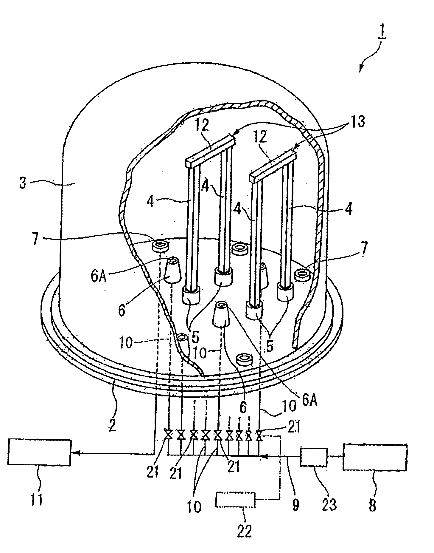
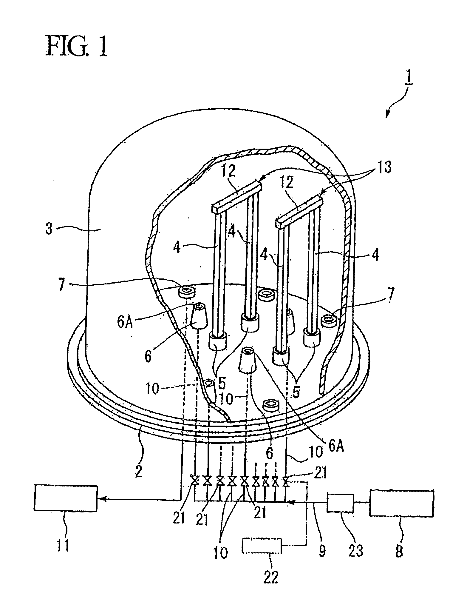
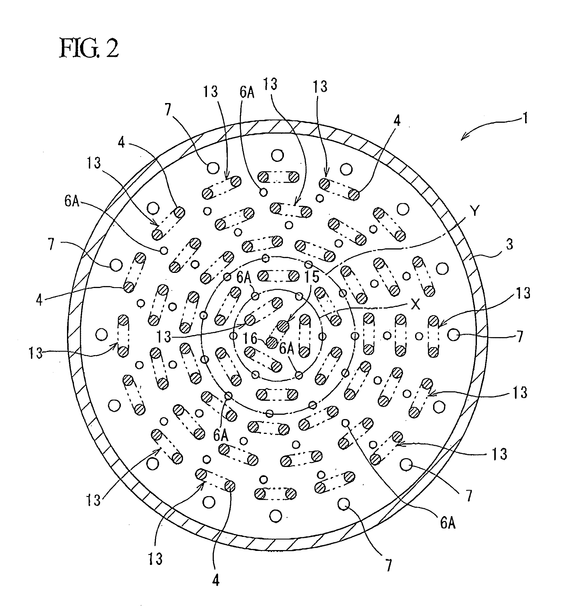
[0066]Sixteen gas ejection ports 6A are selected among the concentrically arranged gas ejection ports 6A without being biased to particular positions, and valves 21 of the gas supplying pipe 10 connected to the selected gas ejection ports 6A are closed. This state is maintained for the 20 minutes. After 20 minutes, sixteen gas ejection ports 6A in an opened state are selected, and while the valves 21 of the gas supplying pipes 10 connected to the selected gas ejection ports 6A are put in the closed state, the valves 21, which have been closed until now, become opened for 20 minutes. This operation is repeated for 34 hours.

control example 2

[0067]Sixteen gas ejection ports 6A are selected among the concentrically arranged gas ejection ports 6A without being biased to particular positions, and valves 21 of the gas supplying pipe 10 connected to the selected gas ejection ports 6A are closed. This state is maintained for the 20 minutes. After the 20 minutes, sixteen gas ejection ports 6A in an opened state are selected, and while the valves 21 of the gas supplying pipes 10 connected to the selected gas ejection ports 6A are put in the closed state, the valves 21, which have been closed until now, become opened for 20 minutes. This operation is repeated for 20 hours. The overall operation duration of “Control Example 2” is shorter than that of “Control Example 1.”

control example 3

[0068]Sixteen gas ejection ports 6A are selected among the concentrically arranged gas ejection ports 6A without being biased to particular positions, and valves 21 of the gas supplying pipe 10 connected to the selected gas ejection ports 6A are closed. This state is maintained for 20 minutes. After the 20 minutes, sixteen gas ejection ports 6A in an opened state are selected, and while the valves 21 of the gas supplying pipes 10 connected to the selected gas ejection ports 6A are put in the closed state, the valves 21, which have been closed until now, become opened for 20 minutes. This operation is repeated for 45 hours. The overall operation duration of “Control Example 3” is longer than that of “Control Example 1.”


PUM

PropertyMeasurementUnit
Fractionaaaaaaaaaa
Fractionaaaaaaaaaa
Fractionaaaaaaaaaa

Abstract

A method for manufacturing polycrystalline silicon with high quality by effectively preventing undesired shape such as giving an rough surface to silicon rods or an irregularity in diameter of the silicon rods. The method for manufacturing polycrystalline silicon includes: an initial stabilizing step of deposition wherein a velocity of ejecting the raw material gas from the gas ejection ports is gradually increased; the shaping step wherein first the ejection velocity is increased at a rate higher than that in the stabilizing step and then the ejection velocity is gradually increased at a rate lower than the previous increasing rate; and a growing step wherein, after the shaping step, the ejection velocity is made slower than that at the end of the shaping step until the end of the deposition.

Description

BACKGROUND OF THE INVENTION[0001]1. Field of the Invention[0002]The present invention relates to a method for manufacturing polycrystalline silicon, which is for manufacturing a polycrystalline silicon rod by depositing polycrystalline silicon on a surface of a heated silicon seed rod.[0003]Priority is claimed on Japanese Patent Application No. 2007-307445, filed Nov. 28, 2007, the content of which is incorporated herein by reference.[0004]2. Description of the Related Art[0005]As one of methods for manufacturing polycrystalline silicon, there has been known a so-called Siemens method used for manufacturing polycrystalline silicon. This method includes heating a plurality of silicon seed rods, arranged within a reaction furnace, supplying a raw material gas which is a mixed gas of chlorosilane gas and hydrogen gas into the reaction furnace thereby bringing the raw material gas into contact with the heated silicon seed rods, and allowing polycrystalline silicon to deposit on surfaces...

Claims


Application Information

Patent Timeline
IPC IPC(8): C23C16/24
CPCC01B33/325
Inventor ENDOH, TOSHIHIDETEBAKARI, MASAYUKIISHII, TOSHIYUKISAKAGUCHI, MASAAKIHATAKEYAMA, NAOKI
Owner HIGH-PURITY SILICON CORP
Why Eureka
Try Eureka