Hemostatic device

a technology of a hemostatic device and a stent, which is applied in the field of hemostatic devices, can solve the problems of poor blood circulation, insufficient hemostatic effect in this pressing direction, and long time-consuming, and achieve excellent hemostatic

Inactive Publication Date: 2009-05-28
TERUMO KK
View PDF24 Cites 36 Cited by
  • Summary
  • Abstract
  • Description
  • Claims
  • Application Information

AI Technical Summary

Benefits of technology

[0010]It is therefore one object of the invention to provide a hemostatic device which has an excellent hemostatic effect.
[0011]A second object of the invention is to provide a hemostatic device which spontaneously (that is, without manipulation by a health care practitioner such as a physician or nurse—sometimes referred to hereinafter as the “operator”) eases over time the pressure applied by the balloon, thus helping to prevent harmful effects from the continued application of pressure, such as numbness, pain and vascular blockage.
[0012]A third object of the invention is to provide a hemostatic device which enables a balloon for compressing a puncture site (a site where blood flow is to be stopped) to be easily positioned at the site, and thus minimizes blood leakage and hematoma formation due to poor positioning of the balloon.

Problems solved by technology

In such prior-art hemostatic devices, the pressure applied to the site where bleeding is to be stopped is directed in a substantially vertically downward direction, and the hemostatic effect in this pressing direction is inadequate.
Therefore, complete hemostatis sometimes does not occur or takes a long time to achieve.
Hence, other tissues are also compressed, including other blood vessels and nerves, sometimes resulting in numbness and poor blood circulation.
To keep this from happening, a health care practitioner such as a physician or nurse must lower the compressive force over time by carrying out manual operations to reduce the balloon pressure or loosen the band, which is inefficient and inconvenient.
It has been pointed out that this makes the balloon difficult to position properly.
In fact, due to poor positioning of the balloon, a hematoma may form or blood leakage may occur because of the inability to stop bleeding.

Method used


Image

  • Hemostatic device
  • Hemostatic device
  • Hemostatic device

Examples


first embodiment

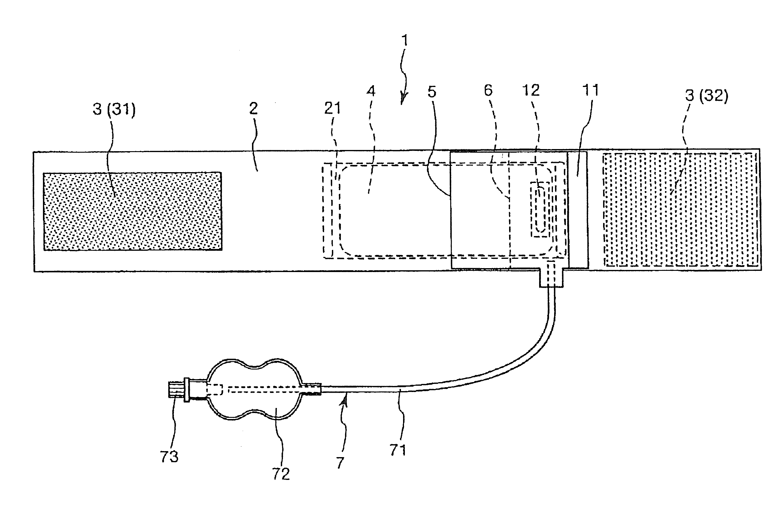
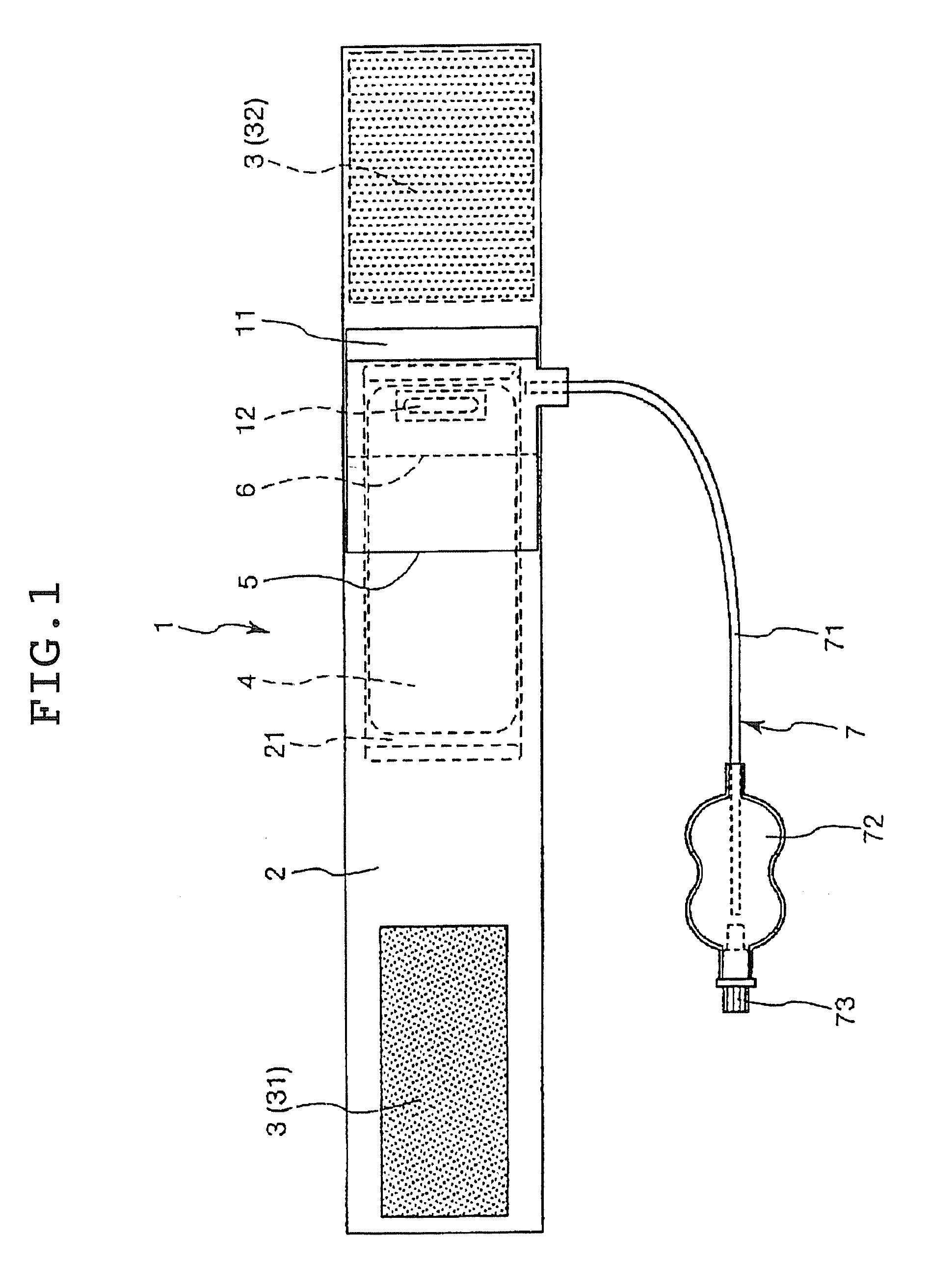
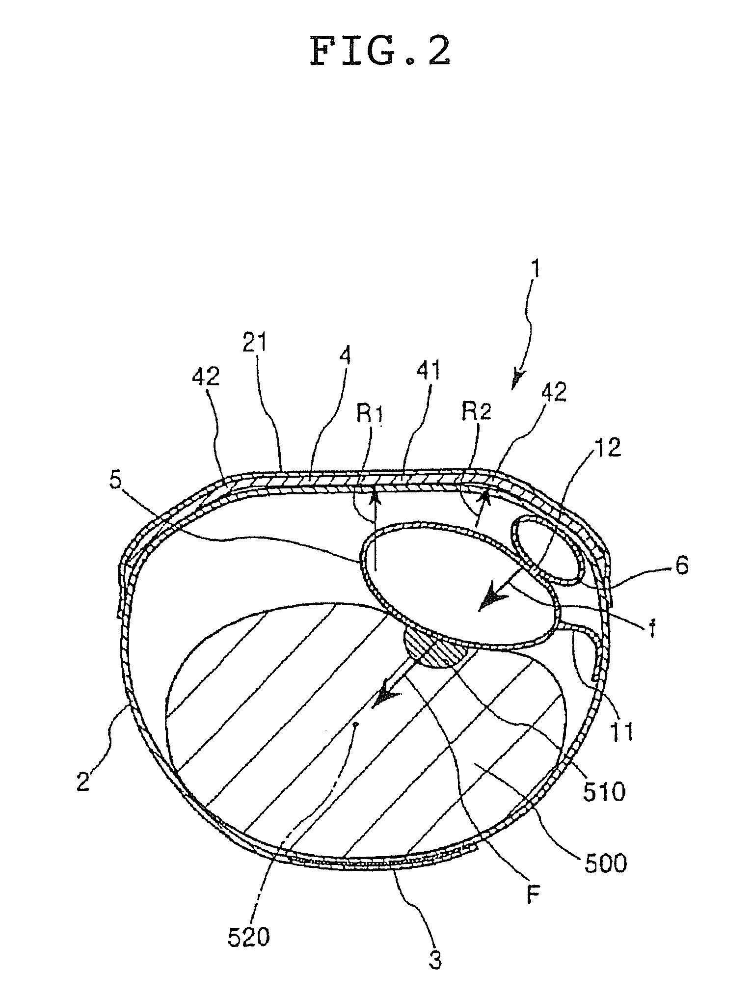
[0080]As noted above, FIG. 1 is a bottom view of a first embodiment of the hemostatic device according to the invention. This shows the side of the device that serves as the inside surface when the device is attached to the wrist of a patient. FIG. 2 is a sectional view showing the same hemostatic device attached and in use on the wrist.

[0081]The hemostatic device 1 shown in FIGS. 1 and 2 is used to stop bleeding at a puncture site 510 following the removal of an instrument such as a catheter which was inserted percutaneously into an artery through a puncture formed somewhere on a limb, such as at a wrist 500, for a medical purpose such as treatment, examination or diagnosis. This hemostatic device 1 has a band 2 which is adapted to be wrapped around the wrist 500, a surface fastener 3 for securing the band 2 in a wrapped state to the wrist 500, a curved plate 4, a main balloon 5 and a secondary balloon 6.

[0082]The band 2 is a flexible belt-like member. As shown in FIG. 2, the band ...

second embodiment

[0121]FIG. 3 is a sectional view showing a hemostatic device according to a second embodiment of the invention during use.

[0122]The hemostatic device 10 in this embodiment has the same features as the hemostatic device 1 in the above-described first embodiment, except that the secondary balloon 6 is connected to the band 2 via a flexible connector 13.

[0123]In the present embodiment, the secondary balloon 6, by being connected to the band 2 via a connector 13 on the same side as the connector 11 for the main balloon 5 (i.e., the right side in FIG. 3), more easily and reliably assumes a tilted orientation. This more readily allows the pressing force f applied to the main balloon 5 to act in an oblique direction (that is, in a direction which causes the main balloon 5 to face substantially the center 520 of the wrist 500), thus enabling a better hemostatic effect to be achieved.

third embodiment

[0124]FIG. 4 is a sectional view showing a hemostatic device according to a third embodiment of the invention during use.

[0125]The hemostatic device 100 in this embodiment has the same features as the above-described first embodiment, except that it lacks a secondary balloon 6.

[0126]That is, in the present embodiment, there is no secondary balloon 6. Instead, the main balloon 5 comes into contact with the curved plate 4 through the band 2. Moreover, the balloon 5 is connected to the band 2 only on one side through a connector 11, thus giving the balloon 5 a somewhat tilted orientation, as shown in FIG. 4. This enables the compression force F applied to the puncture site 510 to act in an oblique direction (that is, in a direction facing the center 520 of the wrist 500). As in the first embodiment described above, the result is that a better hemostatic effect can be obtained.

[0127]Moreover, as in the first embodiment, the balloon 5 is positioned on the connector 11 side (the right sid...


PUM


Abstract

A hemostatic device includes a flexible band adapted to be wrapped around a patient's limb at a site on the limb where bleeding is to be stopped, a portion for securing the band in a wrapped state to the limb, a curved plate which is made of a material more rigid than the band and at least a portion of which is curved toward the inner peripheral side thereof, a main balloon which is provided on the inner peripheral side of the curved plate and which inflates when a fluid is introduced therein, and a pressing member which is provided between the curved plate and the main balloon so that at least a portion thereof overlaps with the balloon and which is adapted for pressing against the balloon. The device provides an excellent hemostatic effect and prevents numbness and poor circulation in areas peripheral to the site of attachment.

Description

[0001]This application is a divisional application of U.S. application Ser. No. 10 / 618,964 filed on Jul. 15, 2003, the entire content of which is incorporated herein by reference.BACKGROUND OF THE INVENTION[0002]1. Field of the Invention[0003]The present invention relates to a hemostatic device, and more particularly to a hemostatic device which is attached to a patient's limb at a site on the limb where bleeding is to be stopped and which, by the inflation of a balloon, applies pressure to the site so as to stop bleeding.[0004]2. Background Art[0005]When a procedure involving the percutaneous insertion of an instrument such as a catheter into a blood vessel is carried out for medical treatment, examination or diagnosis, bleeding at the puncture site must be stopped following subsequent withdrawal and removal of the catheter. Hemostatic devices which are attached by being wrapped around the portion of an arm or leg where the puncture site is located and compress the puncture site wh...

Claims


Application Information

Patent Timeline
Patent Type & Authority Applications(United States)
IPC IPC(8): A61B17/135A61B17/12A61B17/132A61B19/00
CPCA61B17/1325A61B17/135A61B2019/5437A61B2017/12004A61B2017/00907A61B2090/3937
Inventor WADA, SATOSHINUMATA, SHIGEKIYAGI, HIROSHI
Owner TERUMO KK
Why Eureka
Try Eureka