Single Stage Glass Lamination Apparatus and Process

a glass lamination apparatus and single stage technology, applied in the direction of lamination, instruments, spectacles/goggles, etc., can solve the problems of inacceptable use of glass, low productivity of such prior art processes, and slow both processes

Inactive Publication Date: 2009-06-04
BOND BROTHERS CONTRACTING PTY LTD
View PDF10 Cites 9 Cited by
  • Summary
  • Abstract
  • Description
  • Claims
  • Application Information

AI Technical Summary

Benefits of technology

[0011]In one form, each of the heating elements in the array has a fixed pre-determined heating output and is capable of being switched between a dormant cycle during which the heating element is switched off, and a heating duty cycle during which the heating element is switched on. Uniform heating across the width of the glass sheet assembly in step (b) may be achieved by switching each of the heating elements in a given row within the array on to its heating duty cycle at the same time, for the same frequency and for the same duration. Differential heating along the length of the glass sheet assembly in step (b) may be achieved by varying the frequency and duration of the heating duty cycles of the heating elements along the length of the heating chamber such that a heating element which is closer to the leading edge of the glass sheet assembly is switched on for a longer period of time than a heating element closer to the trailing edge of the glass sheet assembly. The frequency and duration of the heating duty cycle of the heating elements may increase uniformly along the length of the oven, reaching peak duration and frequency immediately prior to the pressing station, so that the temperature of the laminating film at the leading edge of the glass sheet assembly reaches bonding temperature immediately prior to the pressing station.

Problems solved by technology

The main problem encountered in the production of laminated glass is that air and / or moisture becomes trapped between the laminating film and the glass surfaces which can cause bubbling of the laminating film which is considered a defect which can render the glass unacceptable for use.
Both processes are very slow, requiring long term post-lamination heating and / or the application of a high pressure cycle after lamination.
As a result, the productivity of such prior art processes is low and they require considerable capital expenditure for the necessary costly apparatus such as autoclaves.
These solutions still require multi-pass operation, high energy consumption and, often, expensive equipment such as high pressure autoclaves which allow limited flexibility in their adaptation for use on various types of glass.

Method used


Image

  • Single Stage Glass Lamination Apparatus and Process
  • Single Stage Glass Lamination Apparatus and Process
  • Single Stage Glass Lamination Apparatus and Process

Examples


example

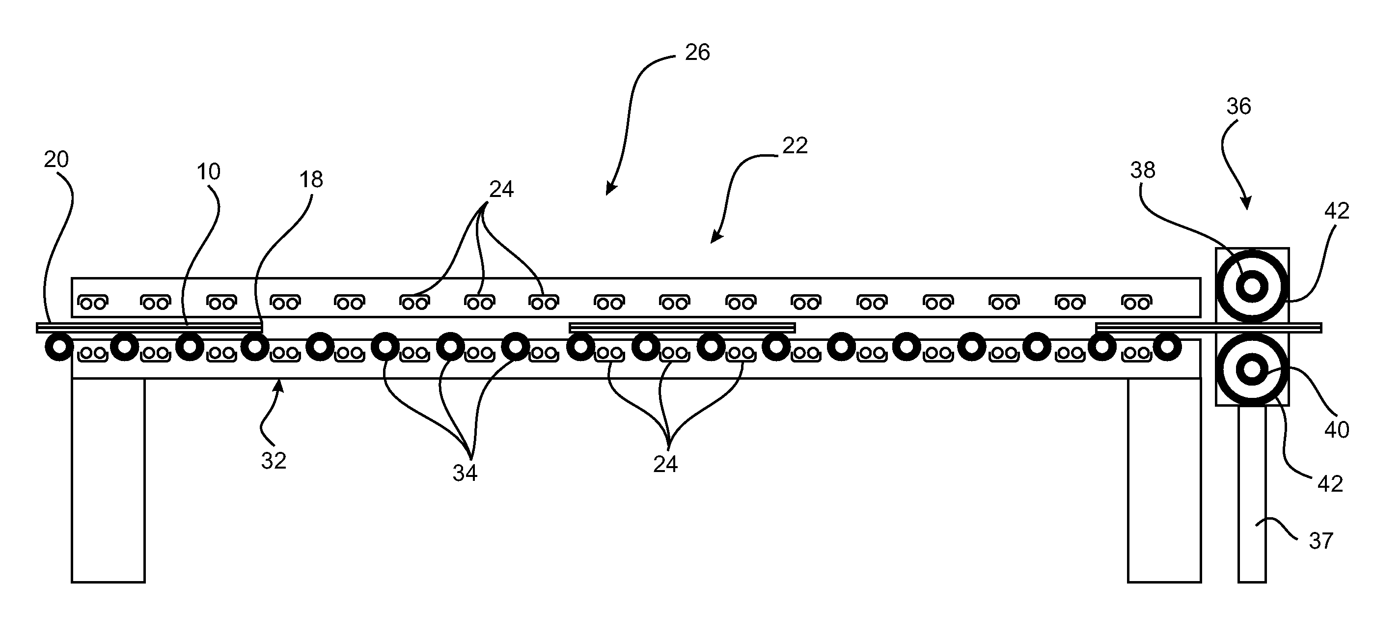
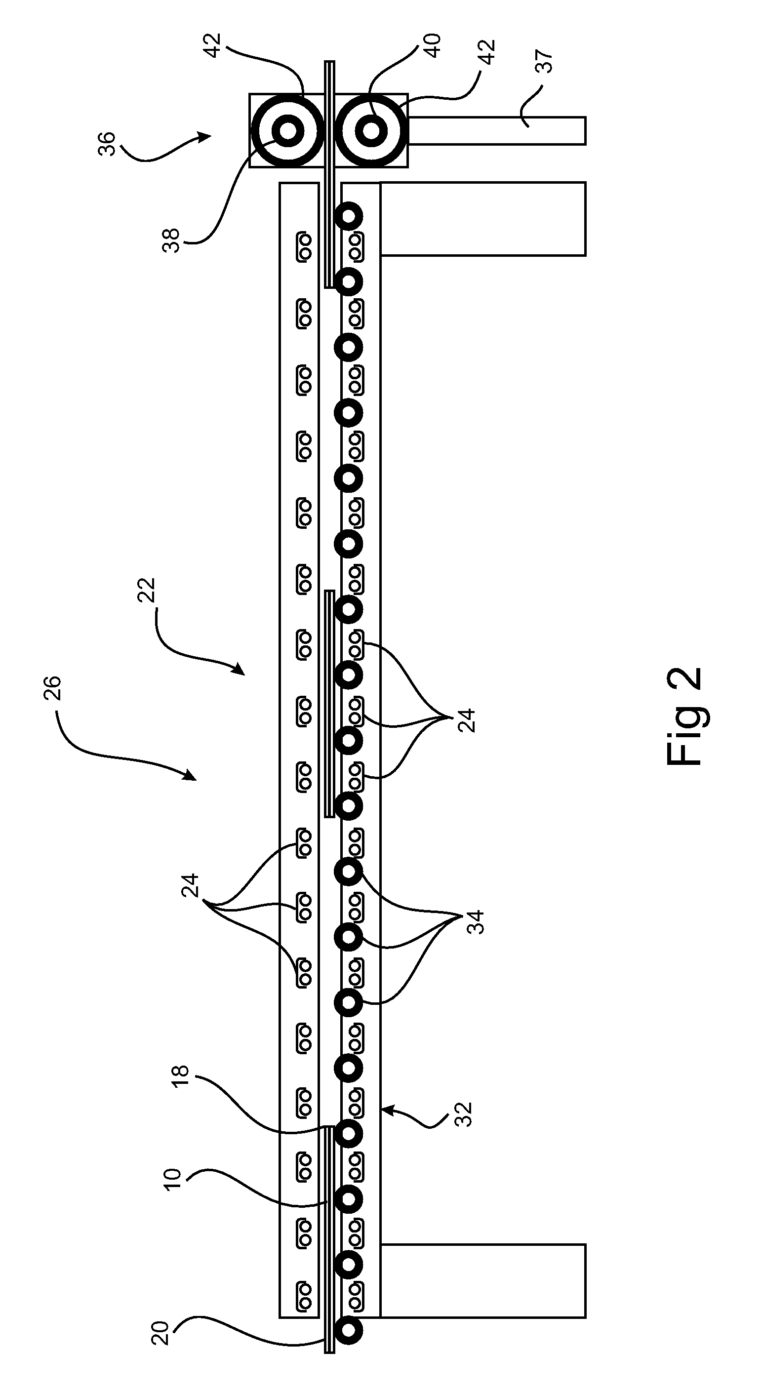
[0053]A single heated zone of 5 m in length and 2.6 m wide, containing an array of 20×5500 watt heating elements in the form of medium wave infrared emitters with gold reflectors arranged to reflect heat towards the glass sheet assembly. The array of heating elements is positioned approximately 100 mm from the exterior faces of the first and second glass sheets. The infrared emitters are evenly spaced across the width and breadth of the oven so that the oven has a heating zone of 2500 mm in length. All measurements of temperature of the glass sheet assembly were recorded using thermocouples placed in between the first glass sheet and the layer of laminating film, approximately 200 mm in from the trailing edge of the glass sheet assembly (one being placed at the centre, one 200 mm in from the left hand side and one 200 mm in from the right hand side). The heat output from the infrared emitters is controlled using three infrared pyrometers—one of the infrared pyrometers is used for co...


PUM

PropertyMeasurementUnit
temperatureaaaaaaaaaa
thicknessaaaaaaaaaa
speedaaaaaaaaaa

Abstract

A glass sheet assembly including a first glass sheet arranged in an opposing parallel configuration with respect to a second glass sheet is provided, with a heat sensitive layer of adhesive laminating film disposed between the first glass sheet and the second glass sheet, the glass sheet assembly having a leading edge and a trailing edge and being of a fixed length and width, the laminating film having a bonding temperature at which melting of the laminating film is initiated. The glass sheet assembly is heated using an array of heating elements so as to cause differential heating along the length of the glass sheet assembly such that the temperature at the leading edge of the glass sheet assembly is higher than the temperature at the trailing edge of the glass sheet assembly with uniform heating across the width of the glass sheet assembly. The first and second glass sheets are pressed toward each other to purge air or moisture from the glass sheet assembly until the first and second glass sheets adhere together via the adhesive laminating film, the step of pressing being initiated at the leading edge of the glass sheet assembly when the temperature of the laminating film at the leading edge of the glass sheet assembly reaches the bonding temperature of the laminating film.

Description

FIELD OF THE INVENTION[0001]The present invention relates to the lamination of glass using a single stage process. The present invention relates particularly, though not exclusively to an infra red heating process.BACKGROUND TO THE INVENTION[0002]Laminates provide a way of strengthening frangible material, for example glass, so as to extend its uses and to render it safer to use in certain circumstances. Laminated glass products can be used for automotive and aircraft glazing, glass doors, balustrades, bulletproofing and many other uses where the glass product must be strong and / or shatterproof. A number of methods for producing such laminates have been disclosed (see, for example, U.S. Pat. Nos. 5,268,049; 5,118,371; 4,724,023; 4,234,533; and 4,125,669). Conventionally, laminated glass is produced by forming a glass sheet assembly or stack which is made up of at least two flat sheets of glass with a layer of polymer adhesive laminating film sandwiched between adjacent sheets. In th...

Claims


Application Information

Patent Timeline
Patent Type & Authority Applications(United States)
IPC IPC(8): B29C65/02
CPCB29C65/1412B29C65/1416B32B17/10862B32B2315/08B32B37/003B32B38/0036B32B2309/02B32B17/10871B32B17/10036B32B17/10761B32B17/10788
Inventor MORGAN, CHRISTOPHERFOSTER, CHRISTINE
Owner BOND BROTHERS CONTRACTING PTY LTD
Why Eureka
Try Eureka