Heat sink device

a heat sink and heat sink technology, applied in the field of heat radiators, can solve the problems of increasing material cost, affecting heat radiation performance, cracking of insulating substrates, etc., and achieve the effects of preventing cracking, excellent thermal conductivity, and improving heat radiation performance for radiating hea

Inactive Publication Date: 2009-06-04
TOYOTA IND CORP +1
View PDF14 Cites 46 Cited by
  • Summary
  • Abstract
  • Description
  • Claims
  • Application Information

AI Technical Summary

Benefits of technology

[0040]According to the heat radiator of par. 1), the stress relaxation member formed of a high-thermal-conduction material and having a stress-absorbing space intervenes between the insulating substrate and the heat sink, and the stress relaxation member is metal-bonded to the insulating substrate and to the heat sink. Thus, excellent thermal conductivity is established between the insulating substrate and the heat sink, thereby improving heat radiation performance for radiating heat generated by a semiconductor device mounted on the insulating substrate. Furthermore, even when thermal stress arises in the heat radiator from a difference in thermal expansion coefficient between the insulating substrate and the heat sink, the stress relaxation member is deformed by the effect of the stress-absorbing space; thus, the thermal stress is relaxed, thereby preventing cracking in the insulating substrate, cracking in a bond zone between the insulating substrate and the stress relaxation member, or warpage of a bond surface of the heat sink bonded to the insulating substrate. Accordingly, heat radiation performance is maintained over a long term. Also, use of the stress relaxation member described in any one of pars. 6) to 20) lowers cost of the stress relaxation member, thereby lowering material cost for the heat radiator.
[0041]According to the heat radiator of par. 2), the stress relaxation member is brazed to the insulating substrate and to the heat sink. Thus, bonding of the stress relaxation member and the insulating substrate and bonding of the stress relaxation member and the heat sink can be performed simultaneously, thereby improving workability in fabrication of the heat radiator. According to the heat radiator described in Patent Document 1, after the insulating substrate and the heat radiation member are soldered together, the heat radiation member and the heat sink must be screwed together; therefore, workability in fabrication of the heat radiator is poor.
[0042]According to the heat radiator of par. 3), the metal layer is formed on a side of the insulating substrate opposite the heat-generating-element-mounting side; the stress relaxation member formed of a high-thermal-conduction material and having a stress-absorbing space intervenes between the metal layer and the heat sink; and the stress relaxation member is metal-bonded to the metal layer of the insulating substrate and to the heat sink. Thus, excellent thermal conductivity is established between the insulating substrate and the heat sink, thereby improving heat radiation performance for radiating heat generated by a semiconductor device mounted on the insulating substrate. Furthermore, even when thermal stress arises in the heat radiator from a difference in thermal expansion coefficient between the insulating substrate and the heat sink, the stress relaxation member is deformed by the effect of the stress-absorbing space; thus, the thermal stress is relaxed, thereby preventing cracking in the insulating substrate, cracking in a bond zone between the metal layer of the insulating substrate and the stress relaxation member, or warpage of a bond surface of the heat sink bonded to the insulating substrate. Accordingly, heat radiation performance is maintained over a long term. Also, use of the stress relaxation member described in any one of pars. 6) to 20) lowers cost of the stress relaxation member, thereby lowering material cost for the heat radiator.
[0043]According to the heat radiator of par. 4), the stress relaxation member is brazed to the metal layer of the insulating substrate and to the heat sink. Thus, bonding of the stress relaxation member and the metal layer of the insulating substrate and bonding of the stress relaxation member and the heat sink can be performed simultaneously, thereby improving workability in fabrication of the heat radiator. According to the heat radiator described in Patent Document 1, after the insulating substrate and the heat radiation member are soldered together, the heat radiation member and the heat sink must be screwed together; therefore, workability in fabrication of the heat radiator is poor.
[0044]With the heat radiator of any one of pars. 6) to 20), cost of the stress relaxation member is lowered, thereby lowering material cost for the heat radiator.
[0045]According to the heat radiator of any one of pars. 6) to 9), the stress relaxation member is deformed by the effect of the stress-absorbing spaces in the form of the through holes; thus, thermal stress is relaxed.

Problems solved by technology

Under some working conditions, thermal stress arises from a difference in thermal expansion coefficient between the insulating substrate and the heat sink and causes cracking in the insulating substrate, cracking in a solder layer which bonds the insulating substrate and the heat sink together, or warpage of a bond surface of the heat sink bonded to the insulating substrate.
Such cracking or warpage impairs heat radiation performance.
However, the heat radiator described in Patent Document 1 must use the heat radiation member formed of a high-thermal-conduction material and a low-thermal-expansion material; thus, material cost is increased.
Furthermore, since the heat radiation member and the heat sink are merely screwed together, thermal conduction therebetween is insufficient, resulting in a failure to provide sufficient heat radiation performance.

Method used


Image

  • Heat sink device
  • Heat sink device
  • Heat sink device

Examples


first embodiment

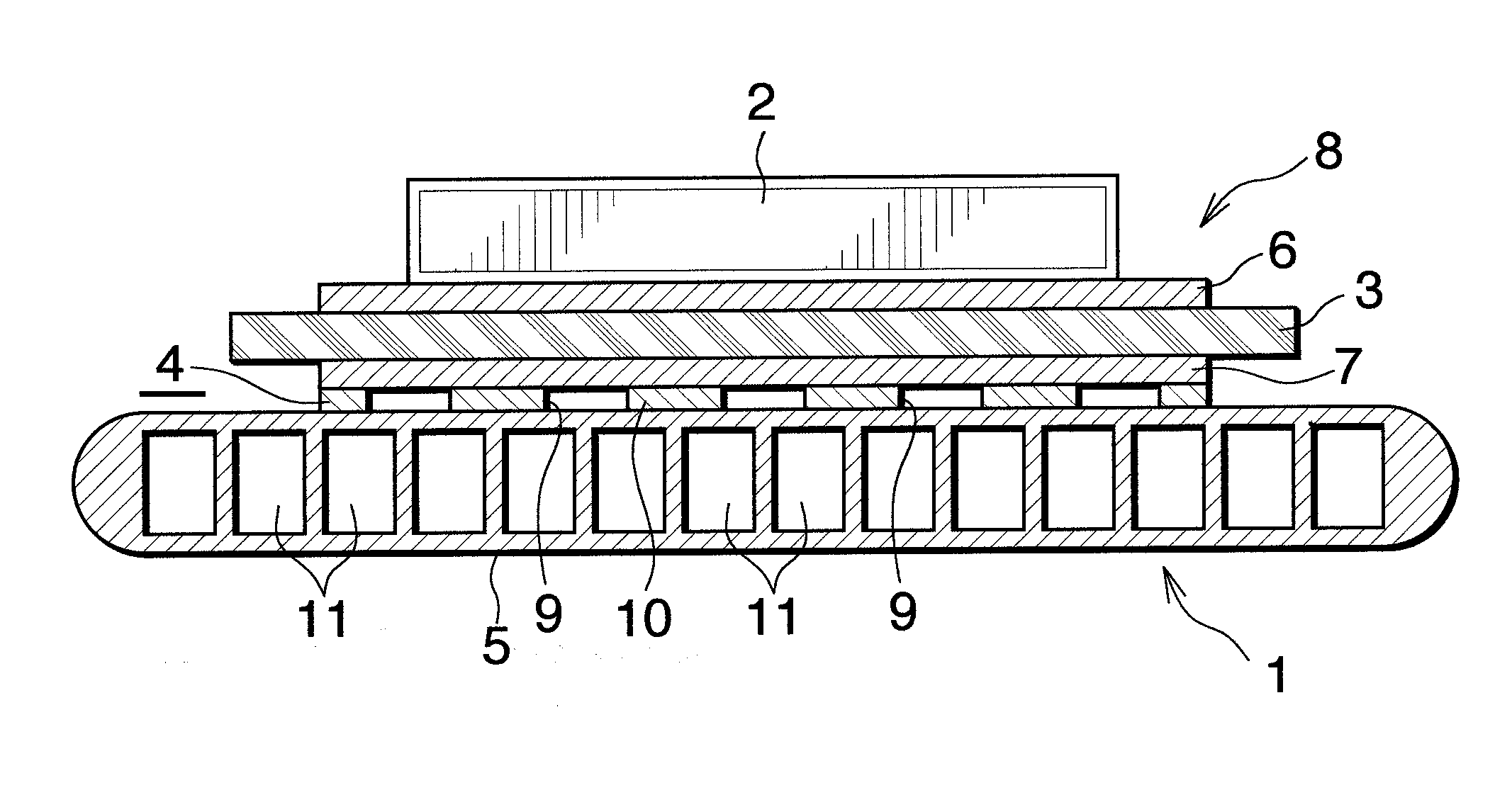
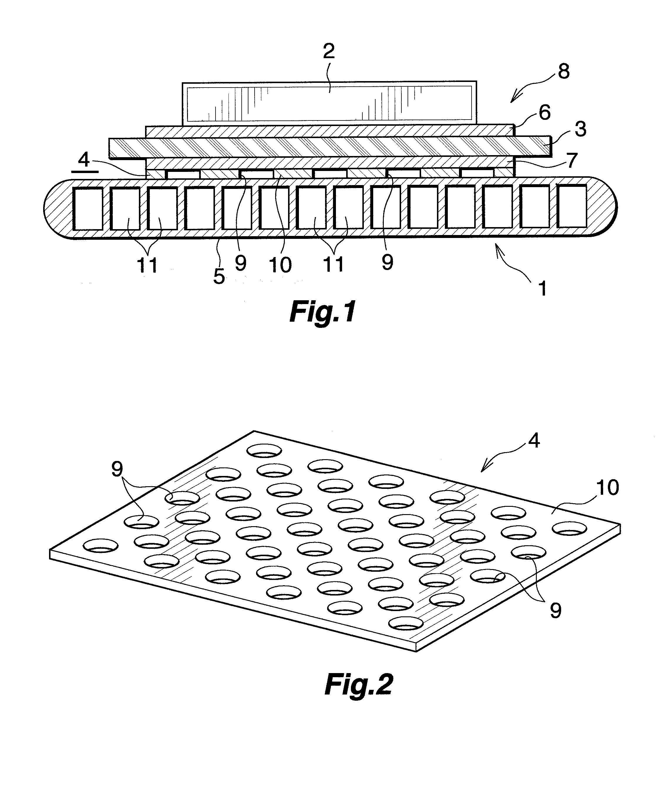
[0056]FIG. 1 shows a portion of a power module which uses a heat radiator of the present invention. FIG. 2 shows a stress relaxation member.

[0057]In FIG. 1, the power module includes a heat radiator (1) and a semiconductor device (2); for example, an IGBT, mounted on the heat radiator (1).

[0058]The heat radiator (1) includes an insulating substrate (3) which is formed of a ceramic and whose upper side serves as a heat-generating-element-mounting side; a stress relaxation member (4) bonded to the lower side of the insulating substrate (3); and a heat sink (5) bonded to the lower side of the stress relaxation member (4).

[0059]The insulating substrate (3) may be formed of any ceramic so long as it satisfies requirements for insulating characteristics, thermal conductivity, and mechanical strength. For example, Al2O3 or AlN is used to form the insulating substrate (3). A circuit layer (6) is formed on the upper surface of the insulating substrate (3), and the semiconductor device (2) is...

second embodiment

[0065]FIG. 3 shows the heat radiator according to the present invention.

[0066]In the case of a heat radiator (15) shown in FIG. 3, the metal layer (7) is not formed on the lower surface of the insulating substrate (3) of the power module substrate (8); i.e., the stress relaxation member (4) is directly brazed to the insulating substrate (3). This brazing is performed in a manner similar to that of the first embodiment described above.

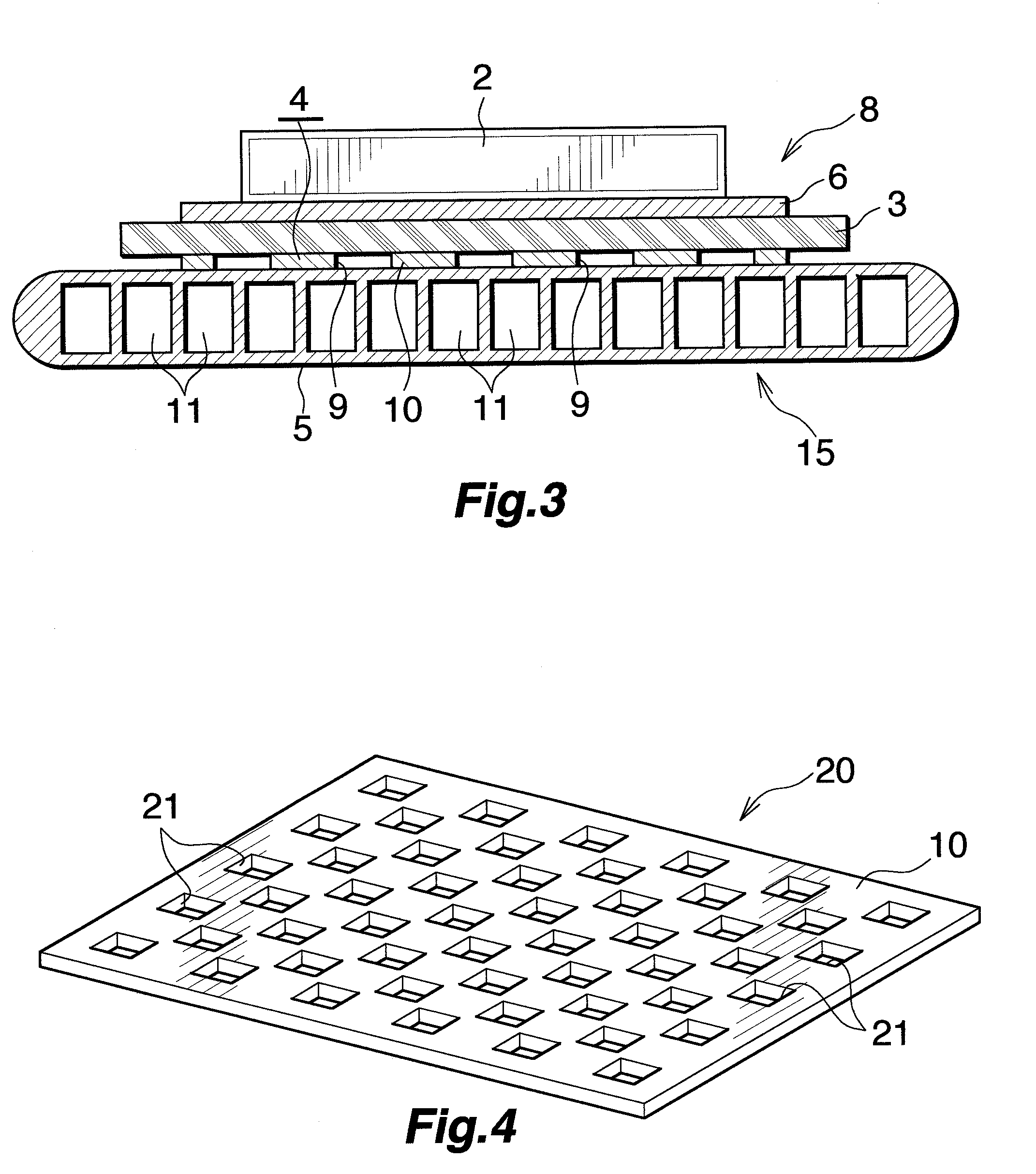
[0067]FIGS. 4 to 21 show modified embodiments of the stress relaxation member.

[0068]A stress relaxation member (20) shown in FIG. 4 is formed of the aluminum plate (10) in which a plurality of rectangular through holes (21) are formed in a staggered arrangement, and the through holes (21) serve as stress-absorbing spaces. The through holes (21) are formed in at least a portion of the aluminum plate (10) which corresponds to a perimetric portion of the insulating substrate (3); i.e., in the entire region of the aluminum plate (10), including a perimetric...

first modified embodiment

[0095]FIG. 4 Perspective view showing the stress relaxation member.


PUM


Abstract

A heat radiator 1 includes an insulating substrate 3 whose first side serves as a heat-generating-element-mounting side, and a heat sink 5 fixed to a second side of the insulating substrate 3. A metal layer 7 is formed on a side of the insulating substrate 3 opposite the heat-generating-element-mounting side. A stress relaxation member 4 intervenes between the metal layer 7 of the insulating substrate 3 and the heat sink 5. The stress relaxation member 4 is formed of an aluminum plate 10 having a plurality of through holes 9 formed therein, and the through holes 9 serve as stress-absorbing spaces. The stress relaxation member 4 is brazed to the metal layer 7 of the insulating substrate 3 and to the heat sink 5. This heat radiator 1 is low in material cost and exhibits excellent heat radiation performance.

Description

TECHNICAL FIELD[0001]The present invention relates to a heat radiator, and more particularly to a heat radiator which includes an insulating substrate whose first side serves as a heat-generating-element-mounting side, and a heat sink fixed to a second side of the insulating substrate and which radiates, from the heat sink, heat generated from a heat-generating-element, such as a semiconductor device, mounted on the insulating substrate.[0002]The term “aluminum” as used herein and in the appended claims encompasses aluminum alloys in addition to pure aluminum, except for the case where “pure aluminum” is specified.BACKGROUND ART[0003]In a power module which uses a semiconductor device, such as an IGBT (Insulated Gate Bipolar Transistor), the semiconductor device must be held at a predetermined temperature or lower by means of efficiently radiating heat generated therefrom. Conventionally, in order to meet the requirement, a heat radiator is used. The heat radiator includes an insula...

Claims


Application Information

Patent Timeline
Patent Type & Authority Applications(United States)
IPC IPC(8): F28F7/00
CPCH01L23/367H01L23/3677H01L23/3735H01L23/473H05K1/0306H05K3/0061H05K3/341H01L2924/0002H05K3/4015H05K2201/0373H05K2201/09681H05K2201/0969H01L2924/00Y02P70/50H01L23/36H01L23/40
Inventor OTOSHI, KOTAKONO, EIJIKUBO, HIDEHITOKIMBARA, MASAHIKOFURUKAWA, YUICHIYAMAUCHI, SHINOBUHOSHINO, RYOICHIWAKABAYASHI, NOBUHIRONAKAGAWA, SHINTARO
Owner TOYOTA IND CORP
Why Eureka
Try Eureka