Motorcycle-use power unit

a technology for power units and motorcycles, applied in the direction of electric propulsion mounting, mechanical actuated clutches, jet propulsion mounting, etc., can solve the problems of reducing the transmission efficiency of oil pressure, increasing and the inability to easily perform maintenance of the clutch control device, so as to suppress the lowering of oil-pressure transmission efficiency and suppress the increase in the weight of the motorcycle. , the effect of reducing the weight of the motorcycl

Active Publication Date: 2009-06-04
HONDA MOTOR CO LTD
View PDF14 Cites 8 Cited by
  • Summary
  • Abstract
  • Description
  • Claims
  • Application Information

AI Technical Summary

Benefits of technology

[0007]The present invention has been made under such circumstances and it is an object of an embodiment of the present invention to provide a motorcycle-use power unit which can easily perform maintenance on a clutch control device while suppressing the lowering of oil-pressure transmission efficiency between a clutch device and a clutch control device and suppressing an increase in the weight of the motorcycle.
[0014]According to an embodiment of the present invention, the clutch control device which performs a changeover of engagement and disengagement of the clutch device and the oil passage which connects the clutch control device and the clutch device with each other are mounted on the outer surface of the clutch cover which is joined to either one of left and right side surfaces of the crankcase in a state that the engine body is mounted on the vehicle body frame. Accordingly, by arranging the clutch control device and the oil passage on the clutch cover in a concentrated manner, it is possible to perform the maintenance of the clutch control device from a side of the engine body whereby the maintenance of the clutch control device can be easily performed. Further, by removing the clutch cover from the crankcase, the clutch control device and the oil passage can be collectively removed from the engine body. Thus, the maintenance of the engine body can be further easily performed. Further, by shortening a length of the oil passage which connects the clutch control device and the clutch device with each other, it is possible to enhance the oil-pressure transmission efficiency while avoiding an increase in the weight of the power unit attributed to the oil passage.
[0015]According to an embodiment of the present invention, since the oil filter which is arranged between the clutch control device and the oil pump is mounted on the clutch cover in a detachable manner from the outside, the maintenance of the oil filter also can be easily performed.
[0016]According to an embodiment of the present invention, the oil discharged from the oil pump flows in the first and second branched oil passages in a bifurcated manner. The first branched oil passage is connected to the clutch control device. The second branched oil passage in the middle of which a pressure-reducing valve mounted on the clutch cover is positioned is connected to another oil-pressure control device. Accordingly, by mounting the large number of parts for the clutch control device and another oil-pressure control device on the clutch cover in a concentrated manner, these parts can be also be removed by merely removing the clutch cover from the crankcase thus facilitating the maintenance of the oil filter. Further, the pressure reducing valve is put in the middle of the second branched oil passage. Thus, it is possible to efficiently assemble a hydraulic system such that an oil pressure suitable for the clutch control device and another oil-pressure control device is applied to these devices.
[0017]According to an embodiment of the present invention, even when the clutch control device includes the individual control means which individually correspond to the first and second clutches of the clutch device constituted as a twin type, the oil filter and both individual control means are arranged at positions different from each other in the vertical direction of the engine body. Accordingly, it is possible to prevent both individual control means and the oil filter from largely projecting sideward from the engine body while mounting both individual control means and the oil filter on the clutch cover.
[0018]According to an embodiment of the present invention, the clutch cover is joined to a side surface of the crankcase on a side opposite to a side stand supported on the vehicle body frame or the engine body in the width direction of the vehicle body frame. Accordingly, when the motorcycle is held in a parking state by erecting the side stand, the clutch cover is directed in the oblique upward direction. Accordingly, it is possible to further enhance the maintenance property of the clutch control device and parts including the oil passages which connect the clutch control device and the clutch device with each other.

Problems solved by technology

Thus, there exists a drawback that the maintenance of the clutch control device cannot be easily performed.
Further, a pipe which connects the clutch device and the clutch control device with each other is elongated thus giving rise to drawbacks wherein a weight of the motorcycle is increased and, at the same time, the transmission efficiency of an oil pressure is lowered.

Method used


Image

  • Motorcycle-use power unit
  • Motorcycle-use power unit
  • Motorcycle-use power unit

Examples


Embodiment Construction

[0035]Hereinafter, a mode for carrying out the present invention is explained in conjunction with one embodiment of the present invention shown in attached drawings.

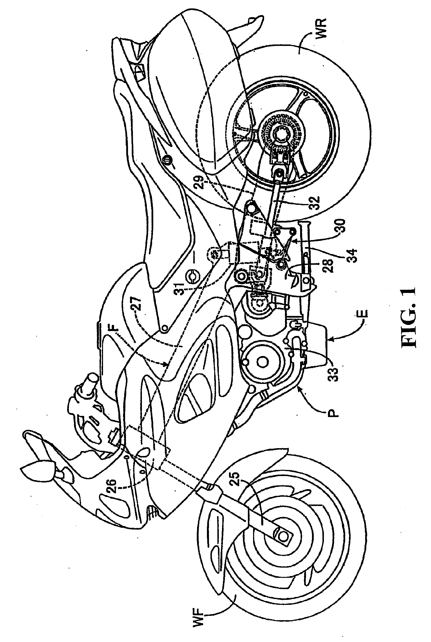
[0036]FIG. 1 to FIG. 14 are views showing one embodiment of the present invention. As illustrated in FIG. 1, a vehicle body frame F of the motorcycle which is a saddle-ride type vehicle includes a head pipe 26 which steerably mounts a front fork 25 pivotally supporting a front wheel WF thereon with a pair of left and right main frames 27 which extends in the rearward and downward direction from the head pipe 26. A pair of left and right pivot plates 28, which is contiguously mounted on rear portions of both main frames 27, extends downwardly. A rear wheel WR is pivotally supported on rear portions of swing arms 29 which have front ends thereof swingably supported on the pivot plates 28. Further, a link 30 is arranged between lower portions of the pivot plates 28 and front portions of the swing arms 29 with a shock absorb...


PUM


Abstract

In a motorcycle-use power unit in which a clutch device arranged in a power transmission path between a crankshaft and a drive wheel is housed in a clutch chamber which is defined between a crankcase and a clutch cover joined to a side surface of the crankcase, the maintenance of the clutch control device can be easily performed while preventing a lowering of oil-pressure transmission efficiency between the clutch device and the clutch control device and preventing an increase in the weight of the motorcycle. A clutch control device performs a changeover of engagement and disengagement of a clutch device by controlling the oil pressure applied to the clutch device. Oil passages for connecting the clutch control device and the clutch device with each other are mounted on a clutch cover.

Description

CROSS-REFERENCE TO RELATED APPLICATIONS[0001]The present application claims priority under 35 USC 119 to Japanese Patent Application No. 2007-310296 filed on Nov. 30, 2007 the entire contents of which are hereby incorporated by reference.BACKGROUND OF THE INVENTION[0002]1. Field of the Invention[0003]The present invention relates to a motorcycle-use power unit including a crankcase which constitutes a portion of an engine body mounted on a vehicle body frame. A clutch device is arranged in a power transmission passage between the crankshaft and a drive wheel so as to engage or disengage the transmission of rotational power of the crankshaft which is rotatably and pivotally supported on the crankcase toward the drive wheel. A clutch cover is joined to either one of left and right side surfaces of the crankcase in a state that the crankcase is mounted on the vehicle body frame so as to form a clutch chamber which houses the clutch device between the clutch cover and the crankcase. A c...

Claims


Application Information

Patent Timeline
Patent Type & Authority Applications(United States)
IPC IPC(8): F16D25/00
CPCF16D25/10F16D25/0638F16D21/06
Inventor OGASAWARA, ATSUSHIFUJIMOTO, YASUSHI
Owner HONDA MOTOR CO LTD
Why Eureka
Try Eureka