Illumination optical apparatus, exposure apparatus, and method for producing device

Inactive Publication Date: 2009-06-04
NIKON CORP
View PDF7 Cites 8 Cited by
  • Summary
  • Abstract
  • Description
  • Claims
  • Application Information

AI Technical Summary

Benefits of technology

[0008]In order to suppress the decrease in the reflectance of the reflecting surface of the reflecting optical member, the degree of vacuum may be improved and raised for the vacuum chamber in which the entire exposure apparatus is accommodated. However, in the case of such a countermeasure, the vacuum gas discharge mechanism is unnecessarily large-sized, and the operation cost of the exposure apparatus is increased.
[0009]Taking the foregoing circumstances into consideration, an object of the present invention is to provide a reflection type illumination technique which makes it possible to decrease the amount of adhesion of minute particles such as debris to the reflecting optical element, without unnecessarily enhancing the ability of the vacuum gas discharge mechanism; an exposure technique which uses the illumination technique; and a technique for producing a device which uses the exposure technique.

Problems solved by technology

However, in the case of such a countermeasure, the vacuum gas discharge mechanism is unnecessarily large-sized, and the operation cost of the exposure apparatus is increased.

Method used


Image

  • Illumination optical apparatus, exposure apparatus, and method for producing device
  • Illumination optical apparatus, exposure apparatus, and method for producing device
  • Illumination optical apparatus, exposure apparatus, and method for producing device

Examples


first embodiment

[0022]The first embodiment of the present invention will be explained with reference to FIGS. 1 to 3.

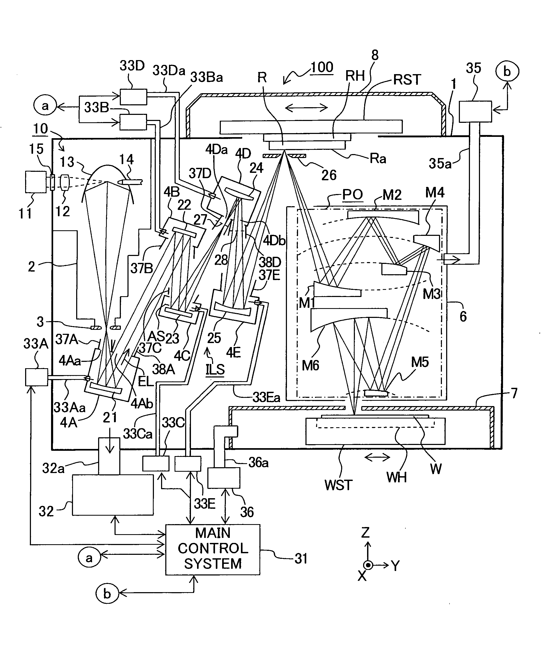
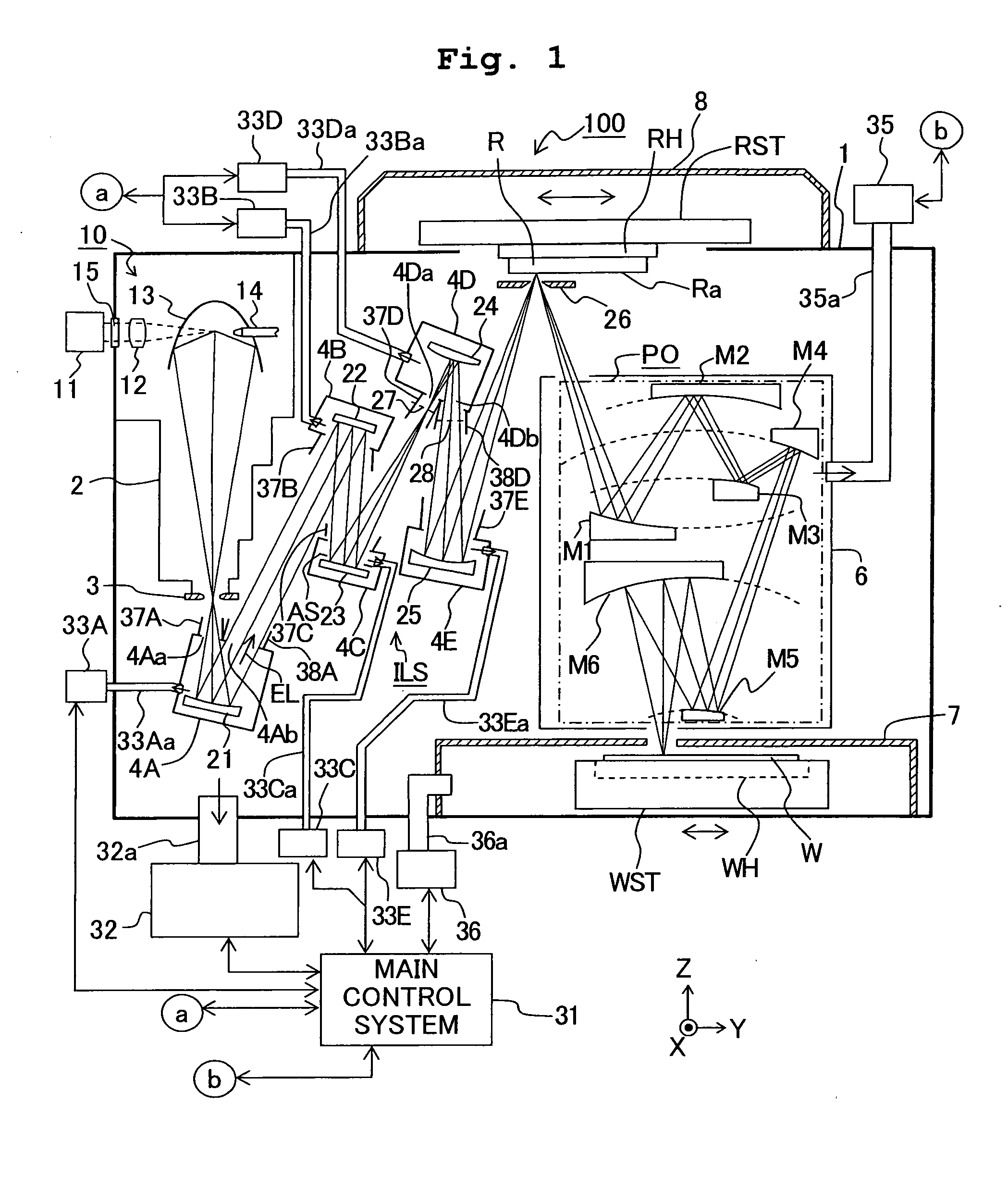
[0023]FIG. 1 shows a sectional view schematically illustrating the overall construction of an exposure apparatus (EUV exposure apparatus), 100 of this embodiment using an EUV light, in which the wavelength is within a range of about 3 to 50 nm, for example, 11 nm or 13 nm, as an exposure light EL (exposure light beam or illumination light). With reference to FIG. 1, the exposure apparatus 100 includes a laser plasma light source 10 which emits the exposure light EL; an illumination optical system (optical system) ILS which illuminates a reticle R (mask) with the exposure light EL; a reticle stage RST which moves the reticle R; and a projection optical system PO which projects an image of a pattern formed on a pattern surface (hereinafter referred to as “reticle surface”) Ra of the reticle R onto a wafer (photosensitive substrate) W coated with a resist (photosensitive material). The ...

second embodiment

[0072]The second embodiment of the present invention will be explained with reference to FIG. 4. In FIG. 4, the components or parts, which correspond to those shown in FIG. 1, are designated by the same or similar reference numerals, the detailed explanation of which will be omitted.

[0073]FIG. 4 shows a sectional view of a schematic construction of an exposure apparatus 100A of this embodiment. With reference to FIG. 4, all of the reflecting optical members from the concave mirror 21 to the concave mirror 25 constructing the illumination optical system ILS are accommodated in an illumination system chamber 4 provided in the vacuum chamber 1. A light source chamber 2 and the illumination system chamber 4 are connected by an aperture plate 3. A small opening, which allows the exposure light EL to pass therethrough, is provided at a partition wall of the illumination system chamber 4 on the optical path for the exposure light EL directed from the concave mirror 25 to the reticle surfac...


PUM


Abstract

A reflection type illumination optical apparatus, which guides an exposure light to a reticle surface via a curved mirror, a concave mirror, etc. includes a vacuum chamber which accommodates the curved mirror, the concave mirror, etc; and a subchamber which is arranged in the vacuum chamber and which accommodates the curved mirror. The subchamber has openings through which the exposure light coming into the curved mirror and the exposure light exiting from the curved mirror pass, respectively. Each of the openings is arranged in the vicinity of a position at which the cross-sectional area of the light flux is smallest. It is possible to decrease the amount of adhesion of minute particles such as debris to the reflecting optical element, without unnecessarily enhancing the ability of the vacuum gas discharge mechanism.

Description

CROSS-REFERENCES TO RELATED APPLICATIONS[0001]This application claims the benefit of priority of U.S. Provisional Application No. 60 / 996,613 filed on Nov. 27, 2007, the entire disclosures of which are incorporated herein by reference.BACKGROUND OF THE INVENTION[0002]1. Field of the Invention[0003]The present invention relates to an illumination optical apparatus of the reflection type which guides an illumination light to a surface of an illumination objective (illumination objective surface), an exposure apparatus provided with the illumination optical apparatus, and a method for producing a device using the exposure apparatus.[0004]2. Description of the Related Art[0005]Recently, in order to enhance the resolution by shortening the exposure wavelength, an exposure apparatus (hereinafter referred to as “EUV exposure apparatus”) has been developed, which exposes a substrate such as a wafer via a reticle (mask) by using, as an exposure light beam (exposure light), an extreme ultravio...

Claims


Application Information

Patent Timeline
IPC IPC(8): G03B27/54F21S8/00G03B27/32
CPCG03F7/702G03F7/70916G03F7/70883G03F7/70841G03F7/20H01L21/0274
Inventor NISHIKAWA, JIN
Owner NIKON CORP
Why Eureka
Try Eureka