
Method and apparatus of recursive time-frequency channel estimation

a time-frequency channel and estimation method technology, applied in the field of communication, can solve the problems of high frequency selectivity channel performance, high computational complexity, and the frequency domain smoothing matrix associated with delay (transform) domain channel estimation tend to become computationally intractable to calculate or too large to store for practical purposes

Active Publication Date: 2009-06-04
NOKIA TECHNOLOGLES OY
View PDF4 Cites 29 Cited by
  • Summary
  • Abstract
  • Description
  • Claims
  • Application Information

AI Technical Summary

Benefits of technology

[0006]Therefore, there is a need to provide a low-complexity approach for time-frequency channel estimation.
[0014]Furthermore, the approach for channel estimation, according to certain embodiments, is advantageous for reception cases where the signal quality (e.g., signal-to-noise ratio (SNR)) is moderate to bad. In such cases computational resources can be freed (from an otherwise computationally intensive interpolation and / or reconstruction filter) and utilized e.g., for improving the quality of the channel estimate using a data assisted approach (e.g., iterative channel estimation based on re-encoding demodulated information bits).

Problems solved by technology

Even though channel estimation based on simple linear interpolation is computationally tractable it tends to perform badly in channels with high frequency selectivity.
However, this approach tends to become computationally intractable even for moderate sized pilot sets.
Also the frequency domain smoothing matrix associated to delay (transform) domain channel estimation tends to become computationally intractable to calculate or too large to store for practical purposes.
However, there are limits as to how small this sliding window can be made before the performance of the channel estimator begins to degrade.
This in turn means that the processing gain of the estimator is upper limited by the size of the window.
Hence, in channels with large coherence bandwidth and / or large coherence time these estimators would be limited by the window size and not the characteristics of the channel.

Method used


Image

  • Method and apparatus of recursive time-frequency channel estimation
  • Method and apparatus of recursive time-frequency channel estimation
  • Method and apparatus of recursive time-frequency channel estimation

Examples


first embodiment

[0071]FIG. 4 shows a schematic block diagram of a receiver part of an OFDM transceiver which can be implemented as a electric circuitry, an integrated chip, a chip set or a receiver module.

[0072]A sampled radio frequency (RF) signal 34 supplied from an RF front end (not shown) is FFT processed in an FFT stage 11 and the FFT processed samples are processed in a pilot estimation (PE) stage 12 to estimate channel values at pilot locations to be used for channel estimation processing in stages 13 to 15. More specifically, the estimated values at the pilot locations are processed in a recursive frequency domain filter stage (RFF) 14 for executing the above described frequency domain processing and then in a recursive time domain filter stage (RTF) 15 for executing the above described time domain processing. Both frequency and time domain filter stages 14, 15 are controlled by a channel adaptation stage 13 configured to adapt the frequency and time domain filter stages 14, 15 to channel ...

second embodiment

[0074]FIG. 5 shows a schematic block diagram of a software-based implementation of the proposed channel estimation mechanism according to a Here, a receiver 30, which may be an integrated chip, a chipset or module, comprises a processing unit 310, which may be any processor or computer device with a control unit which performs control based on software routines of a control program stored in a memory 312. Program code instructions are fetched from the memory 312 and are loaded to the control unit of the processing unit 310 in order to perform the estimation processing steps described above and later in connection with FIGS. 6 and 8. The processing steps may be performed on the basis of input data DI and may generate output data DO, wherein the input data DI may correspond to the RF samples received from the RF front end and the output data DO may correspond to the time-frequency values of the channel estimation result.

third embodiment

[0075]FIG. 6 shows a flow diagram of a channel estimation procedure according to a

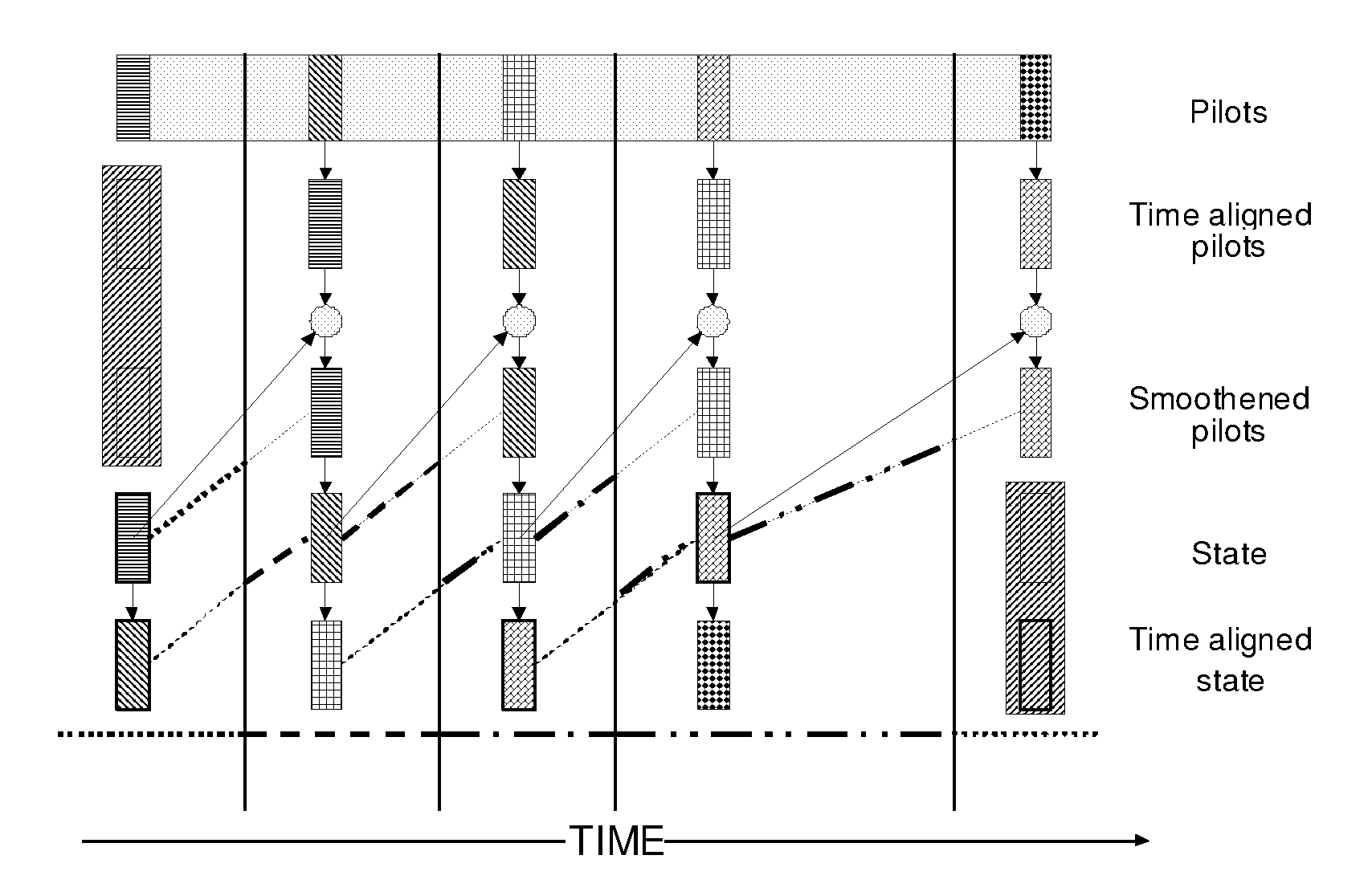
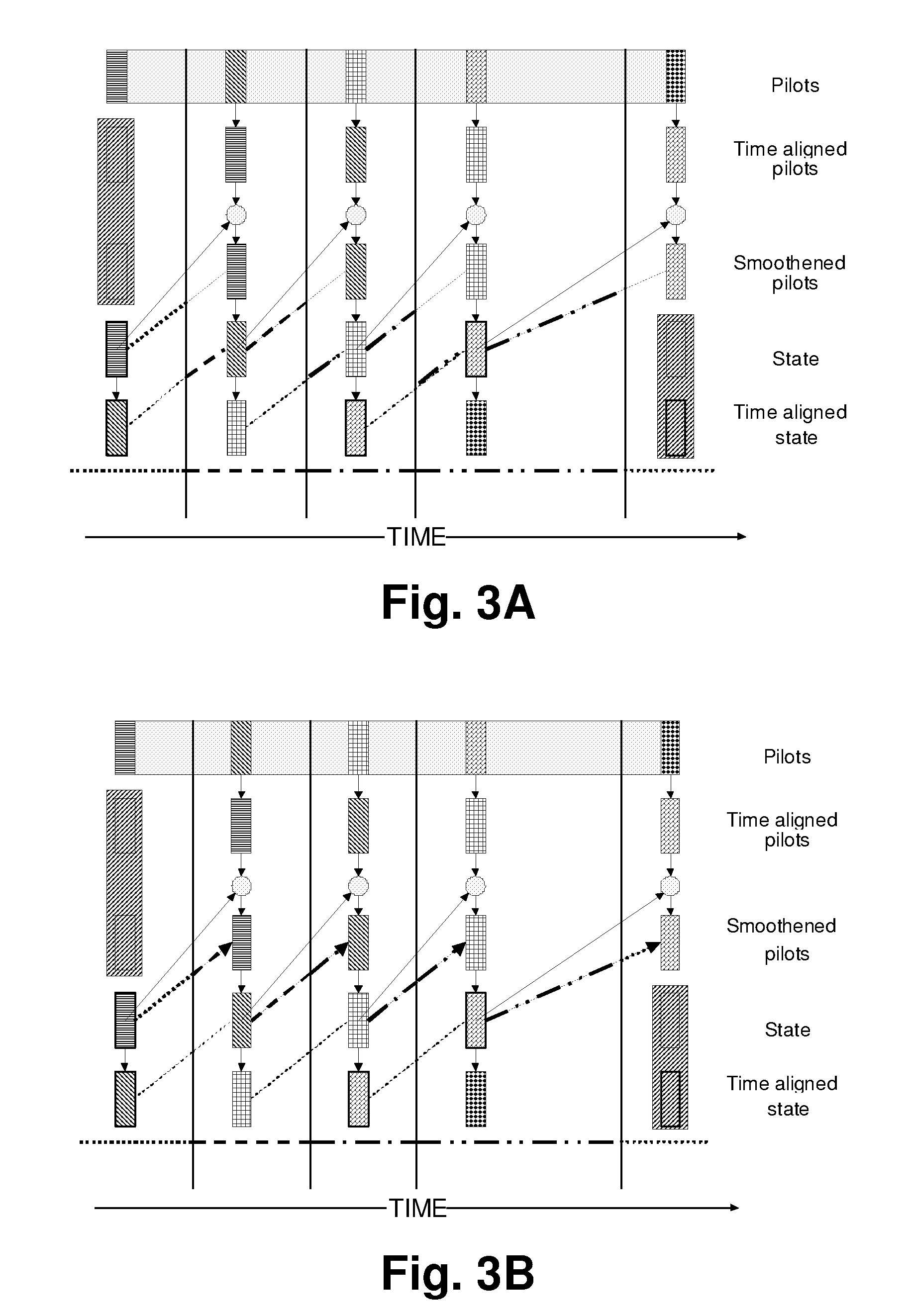
[0076]In step S101 a set of noisy CTF samples is obtained from samples at predetermined pilot locations. Then, in step S102, an FFT processing is performed and each processed CTF sample is divided in step S103 by its associated initial pilot value to derive CTF estimates at pilot locations. Then, in step S104, a recursive frequency interpolation (or extrapolation or smoothing) filtering processing is adapted to the channel conditions, as described above. In step S105, a smoothing processing in the frequency domain is executed by using the adapted filtering processing as described above, and in step S106 an interpolation or extrapolation in the frequency domain is executed by using the adapted filtering processing as described above. Subsequently, in step S107, a recursive time interpolation (or extrapolation or smoothing) filtering processing is adapted to the channel conditions, as described above. Th...


PUM


Abstract

An approach is provided for estimating a channel of a multi-carrier transmission by splitting an interpolation or extrapolation or smoothing of estimates into a frequency domain part and a time domain part, wherein the channel estimation unit is configured to use for both the frequency domain part and the time domain part respective recursive filters, and wherein at least one of the recursive filters is adapted to channel conditions of the multi-carrier transmission.

Description

FIELD OF THE INVENTION[0001]The invention, according to various embodiments, relates to communications, and particularly, to a method, apparatus, and computer program product for estimating a channel of a multi-carrier transmission such as—but not limited to—an orthogonal frequency division multiplexing (OFDM) transmission.BACKGROUND OF THE INVENTION[0002]In multi-carrier systems, e.g., OFDM systems, channel estimation schemes are used for coherent detection of a received signal. OFDM is based on the modulation technique of frequency division multiplexing (FDM). The OFDM technique differs from traditional FDM by having subcarriers, which are orthogonal to each other. The modulation technique used in an OFDM system helps to overcome the effects of a frequency selective channel. A frequency selective channel occurs when the transmitted signal experiences a multipath environment.[0003]The goal of channel estimation is to estimate the time-varying channel frequency response for each OFD...

Claims


Application Information

Patent Timeline
Patent Type & Authority Applications(United States)
IPC IPC(8): H04L27/28
CPCH04L25/022H04L27/2647H04L25/0232
Inventor HOJEN-SORENSEN, PEDROPEDERSEN, MORTEN WITH
Owner NOKIA TECHNOLOGLES OY
Learn More