Stereoscopic video recording method, stereoscopic video recording medium, stereoscopic video reproducing method, stereoscopic video recording apparatus, and stereoscopic video reproducing apparatus

a stereoscopic video and recording medium technology, applied in the field of stereoscopic video recording methods, can solve problems such as eye fatigue, 3d motion sickness, and difficult to perform stereoscopic video recording and reproduction, and achieve the effect of optimizing the recording and reproduction of stereoscopic video

Inactive Publication Date: 2009-06-04
MITSUBISHI ELECTRIC CORP
View PDF9 Cites 399 Cited by
  • Summary
  • Abstract
  • Description
  • Claims
  • Application Information

AI Technical Summary

Benefits of technology

[0014]An object of the present invention is to provide a stereoscopic video recording method, a stereoscopic video recording medium, a stereoscopic video reproducing method, a stereoscopic video recording apparatus, and a stereoscopic video reproducing apparatus that are capable of more optimally performing recording and reproduction of stereoscopic video.
[0016]The stereoscopic video recording method of the preferred embodiment of the present invention calculates an evaluation value that corresponds to the degree of eye fatigue on the basis of the amount of variation, the variation time, and the number of times of the variation, and encodes the video content in such a manner that the evaluation value is within a given range. It is thus possible to produce video content that only involves eye fatigue limited within a certain range and to provide the video content to users.
[0018]The stereoscopic video reproducing method of the preferred embodiment of the present invention displays the maximum parallactic angle value so that the user can recognize the maximum degree of three-dimensionality of the stereoscopic video when viewing the video content, and it is thus possible to objectively grasp the influence of the stereoscopic video on the user.
[0022]The stereoscopic video reproducing apparatus of the preferred embodiment of the present invention considers the location of OSD information in the depth direction when superimposing the OSD information on stereoscopic images, and it is thus possible to further alleviate the eye fatigue caused by the viewing of the OSD information and stereoscopic images.

Problems solved by technology

Viewing stereoscopic (hereinafter referred to also as 3D) video for many hours causes discomforts such as eye fatigue and 3D motion sickness, because the viewer moves the eyes in the focal direction with increased frequency.
Three-dimensional viewing will be problematic especially when the point of attention busily moves in the depth direction.
Also, in particular, the display of subtitles and the like requires continuously switching the eye focus, and may cause more intense discomforts like eye fatigue and 3D motion sickness than the viewing of ordinary 3D video.
Also, as to the recording of stereoscopic video information, when filing a stereoscopic video that employs parallax between right-eye images and left-eye images on an optical disk, it was not possible to handle a video stream including a mixture of flat (hereinafter referred to also as 2D) images and stereoscopic (3D) images.
Particularly, for example, when the display apparatus is switched while the reproducing apparatus is reproducing stereoscopic video, or when a display apparatus is newly connected, information required for 3D display cannot be sent to the display apparatus side in a linked manner, and so the settings in the display apparatus cannot be changed instantaneously.
Also, as to the recording of stereoscopic video information, when filing a stereoscopic video employing parallax between right-eye and left-eye images on an optical disk, there is no video control information that allows recording of broadcasted stereoscopic video and that enables settings in the display apparatus and the reproducing apparatus.
Also, the distribution of stereoscopic video content is affected by the extent of proliferation of compatible display apparatuses, and it is necessary to further set separate regional restrictions for 3D video and for 2D video.
However, conventional systems do not meet such requirements.
Also, it was not possible to superimpose information about the content, copyright information, 3D display scheme information, OSD information, multi-angle information, etc. on a stereoscopic video stream, and therefore it was not possible to instantaneously change the settings on the display apparatus side, not on the reproducing apparatus side.
Also, unlike ordinary 2D video information, 3D video information utilizing parallax includes information for the left-eye and information for the right eye, and the amount of information is doubled and filing efficiency is deteriorated.
Also, while increased eye fatigue occurs during the reproduction of 3D video with an increased degree of three-dimensionality, it was not possible to give a warning to the user in advance according to the degree of three-dimensionality, or to restrict the viewing according to the age of the user.
Also, while increased eye fatigue occurs during the reproduction of 3D video with an increased degree of three-dimensionality, it was not possible to alleviate the three-dimensionality of the content on the reproducing apparatus side.

Method used


Image

  • Stereoscopic video recording method, stereoscopic video recording medium, stereoscopic video reproducing method, stereoscopic video recording apparatus, and stereoscopic video reproducing apparatus
  • Stereoscopic video recording method, stereoscopic video recording medium, stereoscopic video reproducing method, stereoscopic video recording apparatus, and stereoscopic video reproducing apparatus
  • Stereoscopic video recording method, stereoscopic video recording medium, stereoscopic video reproducing method, stereoscopic video recording apparatus, and stereoscopic video reproducing apparatus

Examples


first preferred embodiment

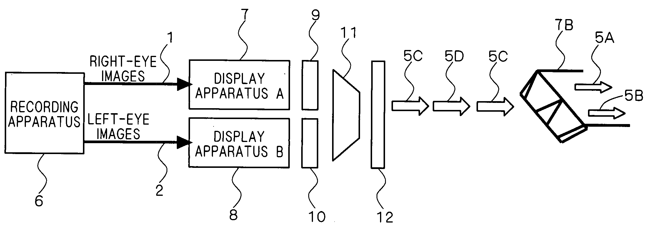
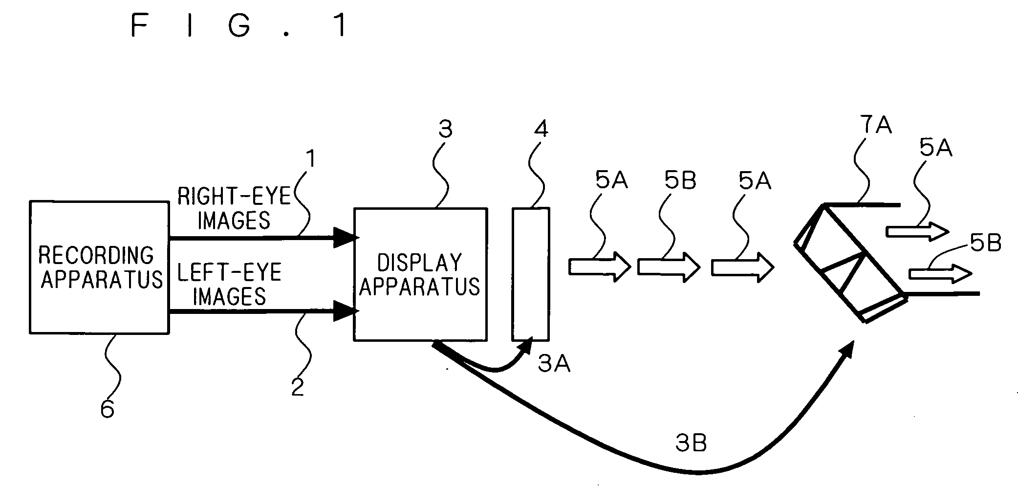
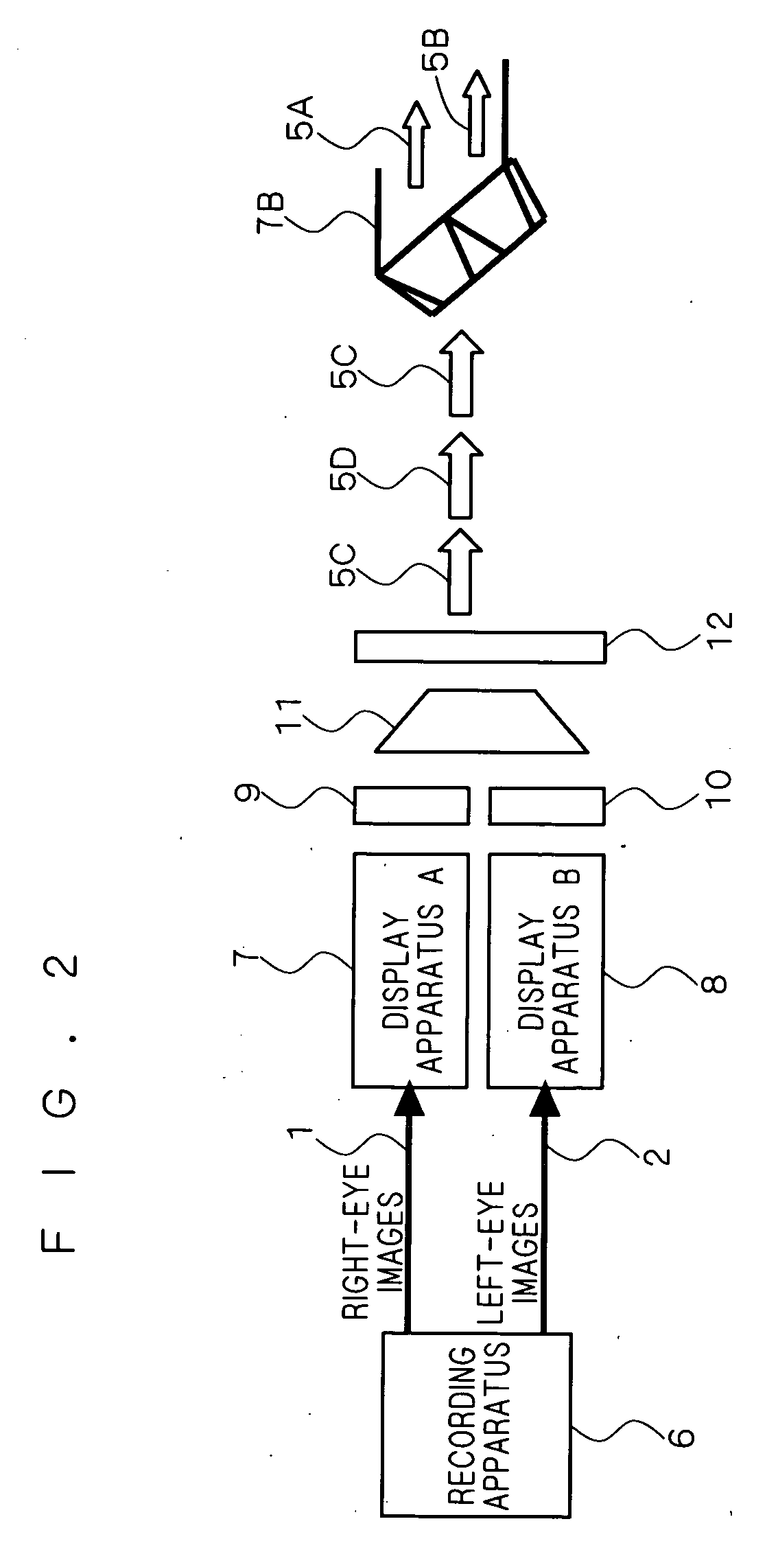
[0064]A first preferred embodiment of the present invention will now be described referring to the drawings. FIG. 1 is a block diagram illustrating the overall configuration of a stereoscopic video system according to this preferred embodiment. The stereoscopic video system shown in FIG. 1 includes a stereoscopic video recording apparatus 6 (which will hereinafter be simply referred to also as a recording apparatus 6) for reproducing a medium that records stereoscopic video and outputting right-eye images 1 and left-eye images 2, a display apparatus 3 such as a TV or a projector, a shutter 4 composed of e.g. liquid crystal and capable of switching two transmissive polarized light rays, and eyeglasses 7A having liquid-crystal shutters on the left and right, or having different polarizing plates on the left and right, so as to view a frame sequence of video images 5A and 5B through the shutter 4. FIG. 2 illustrates another example of the configuration of a stereoscopic video system of...

second preferred embodiment

[0082]Next, a second preferred embodiment will be described referring to the drawings. When stereoscopic images utilizing parallax information, as shown in FIGS. 1 to 3, are intactly broadcasted on television, they are displayed like superimposed images. They cannot be viewed without a dedicated stereoscopic display apparatus constructed as described above. Thus, the broadcasting of stereoscopic video is limited by infrastructural facilities of equipment on the viewer side, and it is necessary to provide a dedicated channel that is not intended to be seen by people in general, or to superimpose a flag on the broadcasted information to indicate that it is 3D. Accordingly, it is generally convenient to distribute such stereoscopic video in the form of a recording medium, and to reproduce it with a dedicated player or with a player having this function. Considering such circumstances, methods and formats for storing stereoscopic video in a recording medium will now be described.

[0083]F...

third preferred embodiment

[0126]Next, a third preferred embodiment will be described. FIG. 24 is a block diagram of a stereoscopic video recording apparatus according to the third preferred embodiment. The stereoscopic video recording apparatus shown in FIG. 24 includes AD converters 146 for digitizing video signals respectively for the right-eye and left-eye images of stereoscopic video utilizing parallax information, motion vector detectors (motion detectors) 147 necessary for video compression in the temporal direction, DCT transform circuits 148 necessary for intra-compression, adaptive quantization circuits 149 necessary for intra-compression, and inverse quantization circuits 150 for local decoders. The stereoscopic video recording apparatus of FIG. 24 also includes variable-length coding circuits 151 necessary for intra-compression, inverse DCT transform circuits 152 for local decoders, frame memories 153 for local decoders, a buffer memory 154 for storing data after compressed, an OSD information enc...


PUM

PropertyMeasurementUnit
parallactic angleaaaaaaaaaa
timeaaaaaaaaaa
image compatibilityaaaaaaaaaa

Abstract

An object of the present invention is to provide a stereoscopic video recording method, a stereoscopic video recording medium, a stereoscopic video reproducing method, a stereoscopic video recording apparatus, and a stereoscopic video reproducing apparatus that are capable of more optimally performing recording and reproduction of stereoscopic video. According to one solving means of the present invention, a stereoscopic video recording method records, in a recording medium, stereoscopic video including left-eye images (2) and right-eye images (1) utilizing parallax information, by using a stereoscopic video recording apparatus (6). From video content that contains stereoscopic images, the method grasps the amount of variation in parallactic angle having a given or larger value, a variation time that the variation in parallactic angle takes, and the number of times that the variation in parallactic angle occurs. The method then calculates an evaluation value that corresponds to the degree of eye fatigue on the basis of the amount of variation, the variation time, and the number of times of the variation, encodes the video content in such a manner that the evaluation value is within a given range, and records the encoded video content in the recording medium.

Description

BACKGROUND OF THE INVENTION[0001]1. Field of the Invention[0002]The present invention relates to a stereoscopic video recording method, a stereoscopic video recording medium, a stereoscopic video reproducing method, a stereoscopic video recording apparatus, and a stereoscopic video reproducing apparatus.[0003]2. Description of the Background Art[0004]With the progress of encoding techniques for compressing digital video signals, it has become possible to implement optical disk apparatuses with excellent searchability and operability by recording compressed video signals to optical disks. Such optical disk apparatuses are free from degradation caused by dubbing, because they record digital video signals instead of analog video signals, and such optical disk apparatuses offer improved reliability because they employ non-contact optical recording and reproduction.[0005]Encoding methods for compressing such digital video signals include the MPEG (Moving Picture coding Experts Group) sta...

Claims


Application Information

Patent Timeline
Patent Type & Authority Applications(United States)
IPC IPC(8): H04N7/26H04N13/00G11B20/10G11B20/12G11B27/00H04N5/85H04N5/92H04N13/239H04N13/243
CPCH04N13/0033H04N19/61H04N13/0048H04N13/0055H04N13/0059H04N13/007H04N13/0239H04N13/0431H04N13/0434H04N13/0438H04N13/0454H04N13/0456H04N2213/002H04N19/597H04N19/70H04N19/46H04N13/004H04N13/239H04N13/144H04N13/156H04N13/161H04N13/189H04N13/194H04N13/183H04N13/334H04N13/337H04N13/341H04N13/356H04N13/359H04N13/361H04N13/243H04N19/176H04N19/44G11B20/10527G11B2020/10611G11B7/00736G11B7/0079G11B2220/2537
Inventor NAGASAWA, MASATOHATANAKA, KEIJIKURISAKI, KAZUHIRO
Owner MITSUBISHI ELECTRIC CORP
Why Eureka
Try Eureka