Timing chain drive unit

Inactive Publication Date: 2009-06-04
TSUBAKIMOTO CHAIN CO
View PDF0 Cites 20 Cited by
  • Summary
  • Abstract
  • Description
  • Claims
  • Application Information

AI Technical Summary

Benefits of technology

[0019]The operation of the synchronizing sprocket in conjunction with the tension side chain guide decreases the peak value of the tension in the tension side of the chain, making it possible to utilize a smaller and lighter chain, and at the same time to realize a reduction in noises due to cyclic changes in tension.
[0020]The provision of a pivoted guide on the tension side of the chain and the addition of a synchronizing sprocket to the guide is structurally simple, and results in a guide structure comparable in weight to that of a conventional tension side guide. Because the chain tension peaks are avoided, a smaller and lighter chain can be used, and the overall size and weight of the timing chain drive unit can be reduced.
[0021]When the cam is in the form of an oval boss having two lobes, the number of teeth on the synchronizing sprocket can be increased and its rate rotation can be reduced by one-half. With this cam configuration, even in the case of a multi-cylinder engine having a relatively large number of intake and exhaust valves, cyclic changes in chain tensio

Problems solved by technology

Accordingly, conventional timing chains are excessively heavy, the overall weight of the drive unit is high, and excessive noise is generated.
Thus, the convent

Method used


Image

  • Timing chain drive unit
  • Timing chain drive unit
  • Timing chain drive unit

Examples


Example

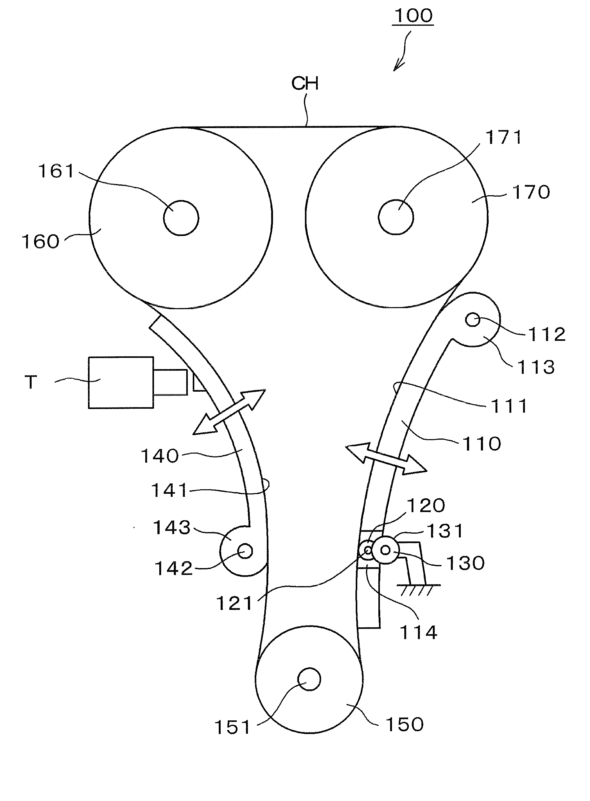
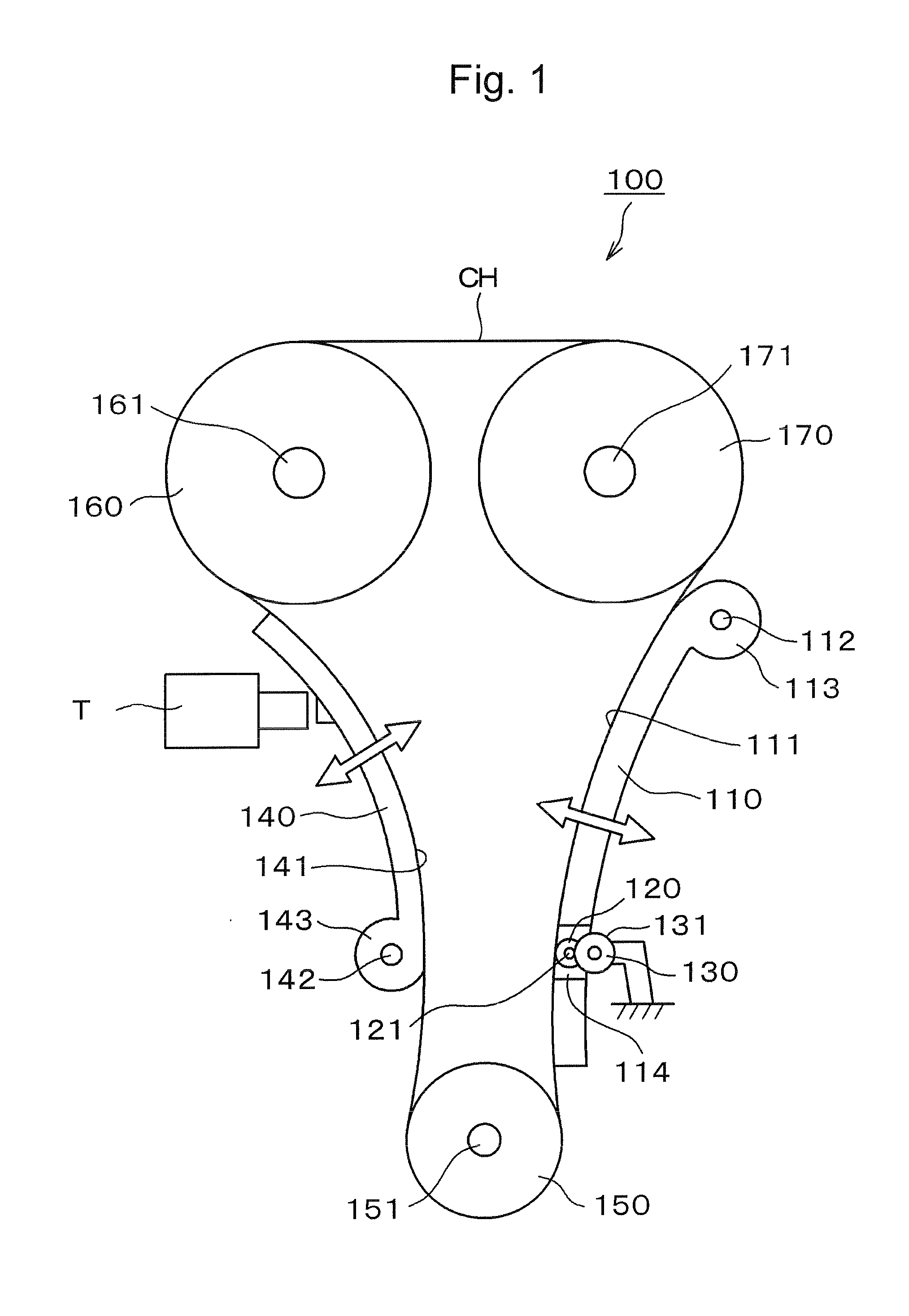
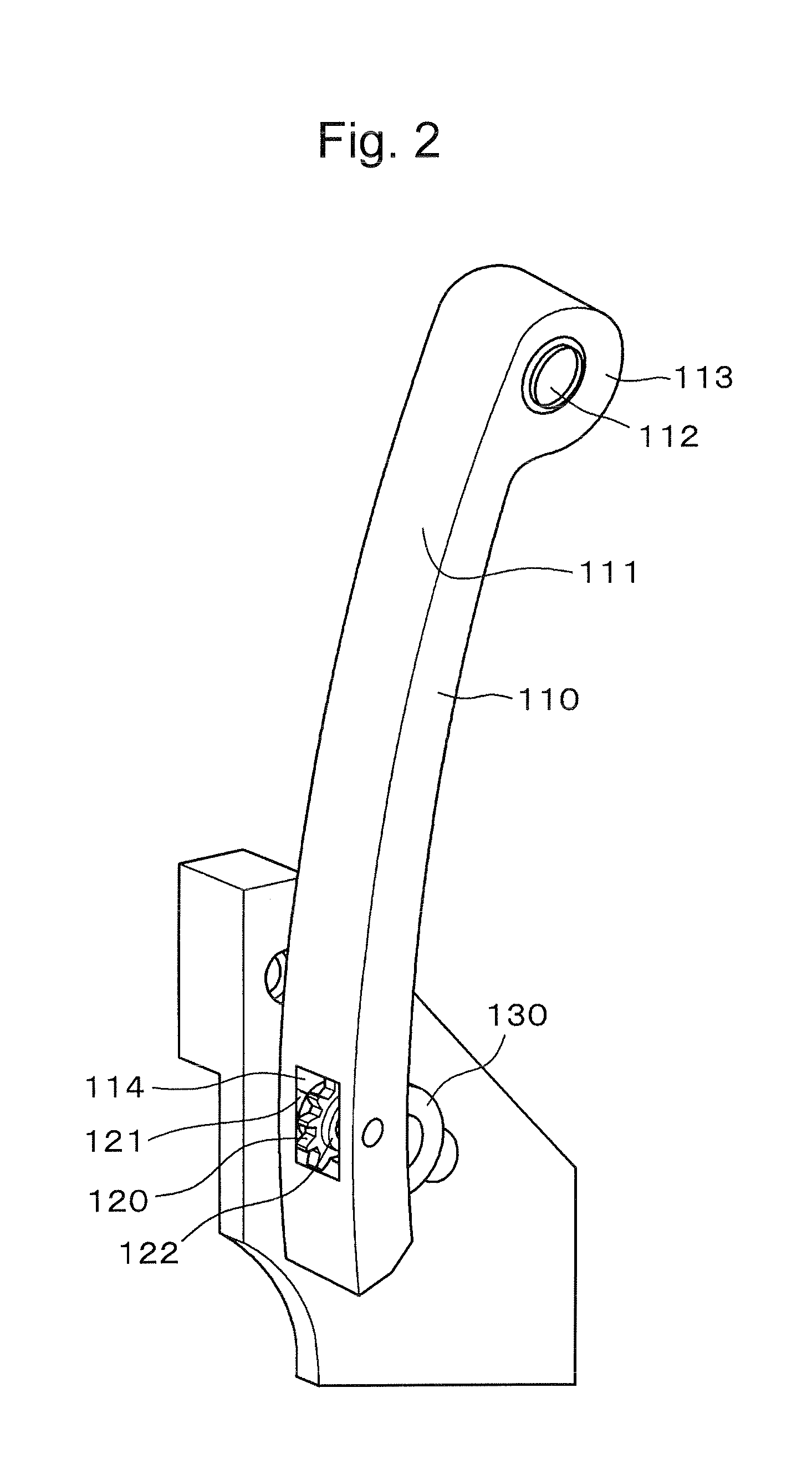
[0038]In accordance with the invention, the tension side of an engine timing chain is arranged to drive a synchronizing sprocket which, in turn, causes a movable chain guide in contact with the tension side of the chain to move in tightening and loosening directions synchronously with the cyclic increase and decrease in tension due to the operation of the engine's intake and exhaust valves. These movements of the chain guide reduce the influence of changes in tension in the chain, and make it possible to use a chain that is smaller in size and lighter in weight than a conventional timing chain having the same loading capability. The use of the synchronizing sprocket improves the quietness of timing drive. The advantages of the invention can be realized in various embodiments, as described below.

[0039]The timing drive according to the invention will ordinarily include a movable guide in sliding engagement with the slack side of the chain and cooperating with a hydraulic tensioner or ...


PUM


Abstract

In an engine timing chain drive, a pivoted chain guide is provided on the tension side of the chain, and a synchronizing sprocket is incorporated into the chain guide and driven by the chain. The synchronizing sprocket rotates a cam which effects reciprocating movement of the guide to compensate for cyclic variations in tension resulting from operation of intake and exhaust valves.

Description

CROSS-REFERENCE TO RELATED APPLICATION[0001]This application claims priority on the basis of Japanese patent application 2007-309909, filed Nov. 30, 2007. The disclosure of Japanese application 2007-309909 is hereby incorporated by reference.FIELD OF THE INVENTION[0002]This invention relates to a timing chain drive unit for transmission of power from the camshaft of an internal combustion engine to one or more camshafts for operating intake and exhaust valves. The invention relates more particularly to improvements in a guide mechanism for controlling tension in a timing chain.BACKGROUND OF THE INVENTION[0003]As shown in FIG. 13, a timing chain drive unit 500 in a dual overhead cam (DOHC) internal combustion engine transmits power by means of a chain CH from driving sprocket 550, to driven sprockets 560 and 570. A pivoted slack-side guide, in sliding contact with a part of the chain CH that travels from the driving sprocket 550 a driven sprocket 560, cooperates with a tensioner T, t...

Claims


Application Information

Patent Timeline
IPC IPC(8): F16H7/08
CPCF01L1/02F01L1/022F16H2007/0897F16H2007/0874F16H2007/0893F16H2007/0802
Inventor NAKANO, YOSHIKAZUKUNIMATSU, KOUHEIHASHIMOTO, HIROSHI
Owner TSUBAKIMOTO CHAIN CO
Why Eureka
Try Eureka