
Method and System for Organ Positioning and Stabilization

a technology applied in the field of organ positioning and stabilization, can solve the problems of insufficient blood flow to various areas of the heart, discomfort of angina, and coronary artery disease, and achieve the effects of reducing the risk of stroke, and improving the quality of li

Inactive Publication Date: 2009-06-04
MEDTRONIC INC
View PDF103 Cites 22 Cited by
  • Summary
  • Abstract
  • Description
  • Claims
  • Application Information

AI Technical Summary

Problems solved by technology

Coronary artery disease remains the leading cause of morbidity and mortality in Western societies.
For example, disease of the coronary arteries can lead to insufficient blood flow to various areas of the heart.
This can lead to the discomfort of angina and the risk of ischemia.
In severe cases, acute blockage of coronary blood flow can result in irreversible damage to the myocardial tissue including myocardial infarction and the risk of death.
The procedure is generally lengthy, traumatic and subject to patient risk.
In general, the body hosts seven potential arterial conduits, the right and left IMAs, the radial arteries and three viceral arteries, one in the abdomen, and two in the lower abdominal wall, though the latter may be quite short and are generally of limited usefulness.
The arrest or stoppage of the heart is generally required because the constant pumping motion of the beating heart would make surgery upon the heart difficult in some locations and extremely difficult if not impossible in other locations
Problems that may be associated with conventional CABG procedures with CPB include the initiation of a systemic inflammatory response due to the interactions of blood elements with the artificial material surfaces of the CPB circuit.
In fact, recent studies have shown aortic clamping and manipulation may release atherosclerotic debris into the bloodstream, resulting in neurologic injury.
However, creation of a technically perfect anastomosis is generally complex, tedious, time consuming and its success is highly dependent on a surgeon's skill level.
The device may however have a lot of foreign material exposed within the blood stream, thus increasing the risk of stenosis and thrombosis.
Intimal damage to both the graft and the target vessel may also occur during delivery of the device.
In addition, the size of the device is strongly related to the size of the vessels.
Problems associated with construction of an anastomosis using a two component intra-luminal mechanical coupling device include mounting of the vessels and connection of the components.
However, mounting of the graft to the coupling device may not be easy.
Damage may occur due to everting of the graft onto the device.
For example, everting of a graft onto a device may cause damage to the intimal layer.
This damage may occur for two reasons: 1) solid grabbing of the vessel wall is necessary to evert an artery, thus one tip of the pair of pincers will roughly touch the intima; and, 2) eversion causes high strain (stretching), which will damage the arteries.
Another problem is that skills are still necessary for proper eversion.
In addition, care must be taken to avoid compression of tissue by the coupling device since compression can cause pressure necrosis.
Problems associated with construction of an anastomosis using a two component extra-luminal mechanical coupling device also include mounting of the vessels and connection of the components.
One area which may create difficulties for the patient and extra expense and time for a stopped heart CABG procedure involves CPB.
Problems may develop during cardiopulmonary bypass due to the reaction blood has to non-endothelially lined surfaces, i.e. surfaces unlike those of a blood vessel.
This may, in turn, increase the risk of hemorrhage.

Method used


Image

  • Method and System for Organ Positioning and Stabilization
  • Method and System for Organ Positioning and Stabilization
  • Method and System for Organ Positioning and Stabilization

Examples


Embodiment Construction

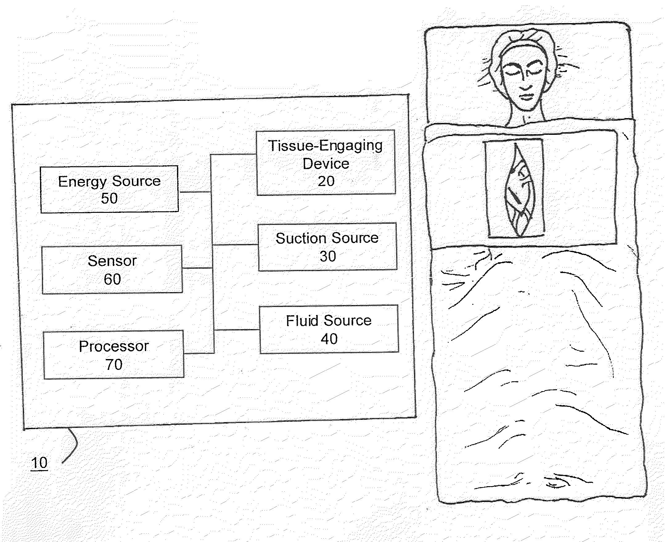
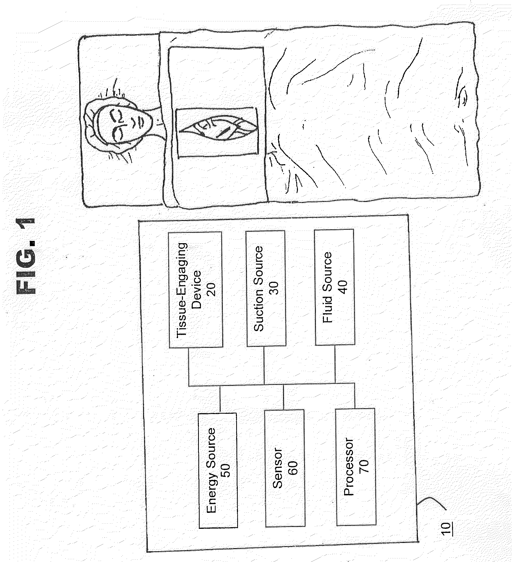
[0085]FIG. 1 shows a schematic view of one embodiment of system 10 for positioning, manipulating, holding, grasping, immobilizing and / or stabilizing tissue in accordance with the present invention. In this embodiment, system 10 is shown to comprise tissue-engaging device 20, a suction source 30, a fluid source 40, an energy source 50, a sensor 60 and a processor 70. System 10 may also include an indifferent electrode, a drug delivery device and / or an illumination device (all not shown in FIG. 1). The indifferent electrode may be placed on the patient's body such as the back, thigh or shoulder or another site other than the suction site. The drug delivery device may be used to deliver drugs to a patient. The illumination device may be used to illuminate a surgical site.

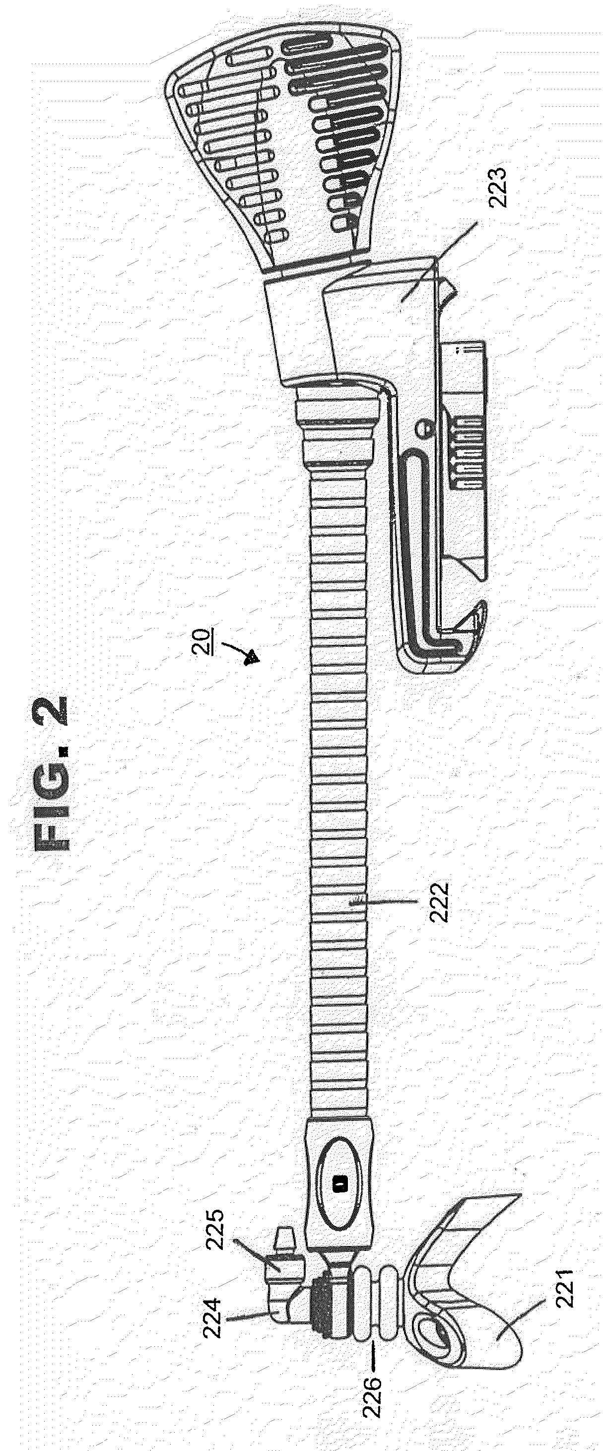
[0086]As shown in FIG. 2, in one embodiment of the present invention, tissue-engaging device 20 may comprise a tissue-engaging head 221, a support apparatus 222 and a clamping mechanism 223 for attaching device 20 to a...


PUM


Abstract

This invention provides a system and method for positioning, manipulating, holding, grasping, immobilizing and / or stabilizing a heart including one or more tissue-engaging devices, one or more suction sources, one or more fluid sources, one or more energy sources, one or more sensors and one or more processors. The system and method may include an indifferent electrode, a drug delivery device and an illumination device. The system's tissue-engaging device may comprise a tissue-engaging head, a support apparatus and a clamping mechanism for attaching the tissue-engaging device to a stable object. The system may be used during various medical procedures including the deployment of an anastomotic device, intermittently stopping and starting of the heart, ablation of cardiac tissues and the placement of cardiac leads.

Description

CROSS-REFERENCE TO RELATED APPLICATIONS[0001]This is a divisional of U.S. patent application Ser. No. 10 / 156,315, filed May 28, 2003, which in turn is a continuation of U.S. patent application Ser. No. 09 / 879,294, filed Jun. 12, 2001 and now U.S. Pat. No. 6,447,443, which in turn claims the benefit under 35 U.S.C. § 1.119(e) from U.S. Provisional Patent Application Ser. Nos. 60 / 261,343, filed Jan. 13, 2001; 60 / 263,739, filed Jan. 24, 2001; 60 / 282,029, filed Apr. 6, 2001; and 60 / 286,952, filed Apr. 26, 2001, which applications are incorporated herein by reference in their entirety.FIELD OF THE INVENTION[0002]This invention relates generally to a system and method for positioning an organ, and more particularly to a system capable of positioning, manipulating, stabilizing and / or holding a heart during cardiac surgery. This invention also relates to a positioning system and method that includes monitoring one or more chemical, physical or physiological characteristics of a bodily tissu...

Claims


Application Information

Patent Timeline
Patent Type & Authority Applications(United States)
IPC IPC(8): A61B18/14A61B17/00A61B17/02A61B17/22A61B17/28A61B17/30A61N1/36
CPCA61B17/0206A61B17/22004A61N1/36114A61B2017/2905A61B2017/308A61B2017/0243
Inventor KEOGH, JAMES R.JAHNS, SCOTT E.COLSON, MICHAEL A.MONTPETIT, KARENDAIGLE, THOMASGUBBIN, DOUGLAS H.GUENST, GARY W.OLIG, CHRISTOPHERPIGNATO, PAUL A.O'NEILL, WILLIAM G.JOLLY, KATHERINE
Owner MEDTRONIC INC
Learn More