Transit time ultrasonic flow measurement

a technology of ultrasonic flow and transcutaneous energy transfer, which is applied in ultrasonic/sonic/infrasonic diagnostics, instruments, applications, etc., can solve the problems of neurological damage, shunt dysfunction, and inability to re-absorb csf at the proper rate, and achieve the effect of improving the accuracy of measurement and measurement results

Inactive Publication Date: 2009-06-04
TRANSONIC SYST
View PDF21 Cites 62 Cited by
  • Summary
  • Abstract
  • Description
  • Claims
  • Application Information

AI Technical Summary

Benefits of technology

[0044]FIG. 14 is a graph of data from a sheep in-vivo study, in which flow was stopped to assess the effects of sheep motion on flow zero offset, wherein the graph shows how changes in zero offset track changes in the received signal voltage amplitude.

Problems solved by technology

However, if blockages exist in the circulation pathways of CSF, the CSF can't be reabsorbed by the body at the proper rate.
If left untreated, the increased intracranial pressure can lead to neurological damage and may result in death.
In addition, it has been found that in some persons with adult-onset dementia of the Alzheimer's type there is dysfunction of the cerebrospinal fluid resorptive mechanism, leading to the retention in the cerebrospinal fluid of substances which result in the histologic lesions associated with adult-onset dementia of the Alzheimer's type, or which are neurotoxic, or both.
The existence of shunt dysfunction further complicates treatment.
Hydrocephalic shunt dysfunction diagnosis is one of the most complicated and time consuming aspects of treating hydrocephalic infants and young children.
However, pediatric hydrocephalic patients have a high risk of shunt dysfunction.
Diagnosis of shunt dysfunction is particularly challenging with preverbal children as such children cannot describe critical symptoms such as headaches.
Unfortunately, the absence of an objective shunt dysfunction diagnostic method leads to delayed treatment or unnecessary intervention.
However, none of these methods actually measure the volumetric flow in the shunt.
This method is often inconclusive since the reservoir is typically made of relatively soft materials that can be easily distorted and depressed without creating any fluid motion.
However, this technique risks shunt infection; does not diagnose the other parts of the shunt system; can be inconclusive in patients with small ventricles and low pressure; and results can be complicated by physiological disturbances caused by a child expressing severe pain and distress.
While these tests can determine shunt patency and shunt flow, this may not be a preferred procedure in many instances since it requires involved expensive studies that will provide readings only while the patient is restrained to a fixed position rather than the dynamic flow picture under different patient conditions such as sitting up and lying down.
These scans are readily available in most hospitals, and the CT scan can define CSF volumes and changes in ventricular volume, but the CT scan cannot measure flow.
Finally, each scan exposes the patient to additional radiation, a well known health hazard.
Since no such cells are present in the CSF, a Doppler sensor is not commercially available.

Method used


Image

  • Transit time ultrasonic flow measurement
  • Transit time ultrasonic flow measurement
  • Transit time ultrasonic flow measurement

Examples


Embodiment Construction

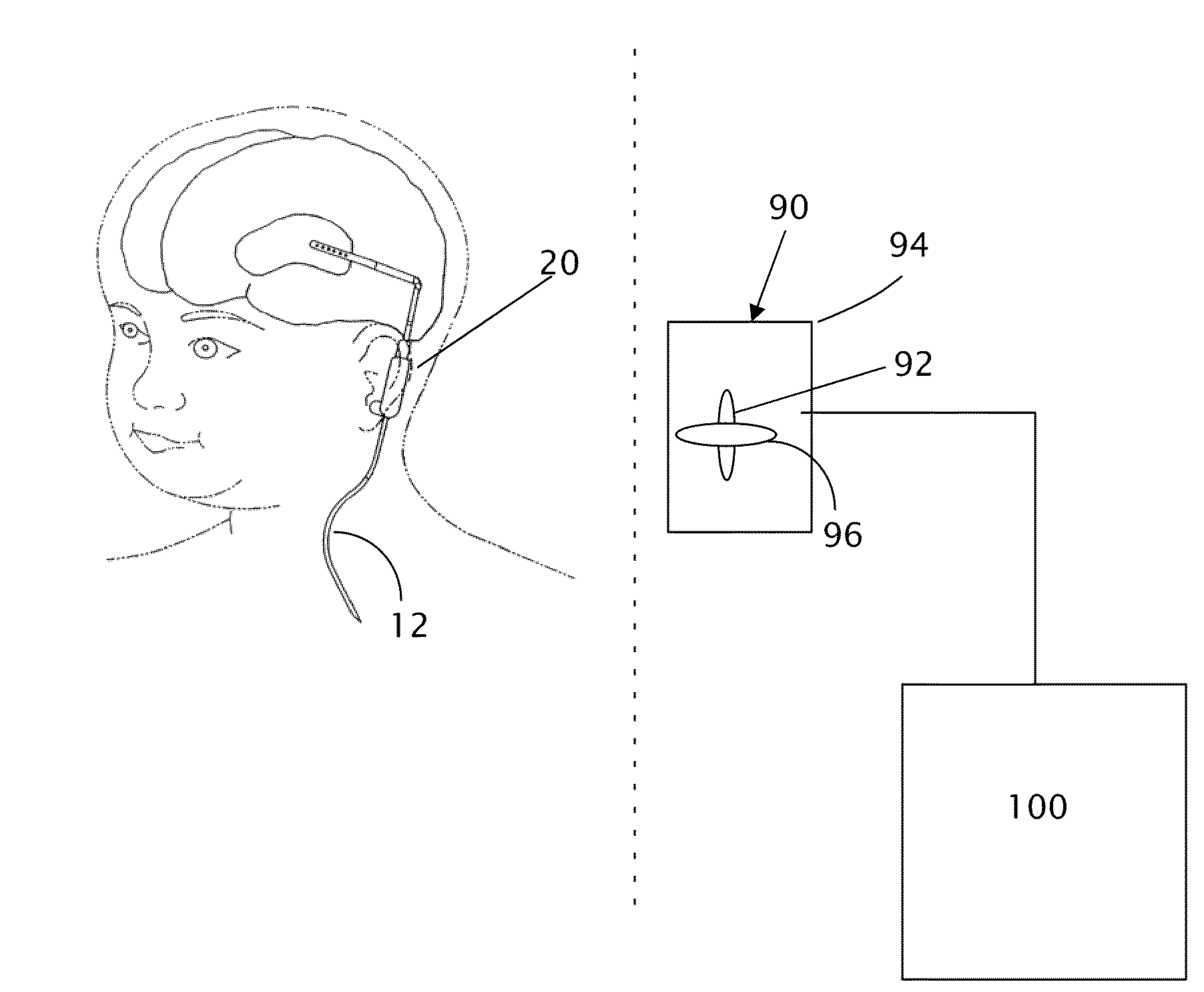
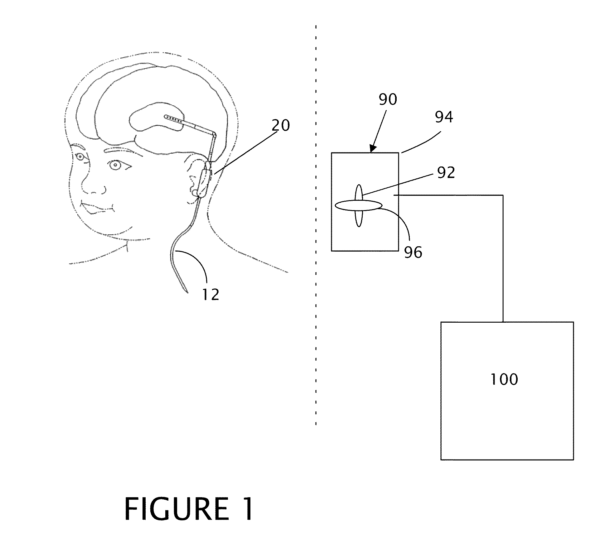
[0052]The present disclosure provides a transcutaneous energy transfer (TET) system, wherein the TET system can be employed to transfer power and signal energy between any of a variety of subcutaneous devices, which include implanted biological support devices and sensors. The biological support devices include pumps for introducing medicines, tracers or indicators, dispensers, heaters, coolers and even electrical stimulators. The implanted sensors include flow, pressure, ECG, EEG, EMG, PH, and blood properties. For purposes of description, the present description is set forth in terms of an implanted ultrasonic transit time flow sensor. Further, although the present flow measurements are set forth in terms of low flow shunt measurements and particularly hydrocephalic shunts, the invention is not limited to such specific systems. The flow sensor and the transcutaneous energy and signal transfer are not so limited and can be employed in any of a variety of applications, such as biome...


PUM


Abstract

A transcutaneous energy transfer system with subcutaneous non coupled coils is used to transmit power and signals to an implanted biological support device or sensor, such as a flow sensor for measuring relatively low flow rates, such as hydrocephalic shunt flow. The flow sensor is configured to convert a shear wave generated by a transducer to a longitudinal wave at the interface of a signal pathway and the flow, wherein the longitudinal wave travels parallel to the flow and exits a flow channel to convert to a shear wave which intersects a second transducer. The transcutaneous energy transfer employs a pair of inductive coupling coils, wherein the coils are disposed in zero coupling orientation which can include a perpendicular orientation of corresponding coil axes.

Description

CROSS-REFERENCE TO RELATED APPLICATIONS[0001]The present application claims the benefit of U.S. provisional patent application No. 61 / 004,858, filed Nov. 30, 2007.STATEMENT REGARDING FEDERALLY SPONSORED RESEARCH OR DEVELOPMENT[0002]This invention was made with government support under Research supported under Phase-I SBIR (Small Business Innovative Research) Grant #1R43 NS049680-01A1 from the National Institute of Neurological Disorders and Stroke of the National Institutes of Health. The government has certain rights in the invention.REFERENCE TO A “SEQUENCE LISTING”[0003]Not applicable.BACKGROUND OF THE INVENTION[0004]1. Field of the Invention[0005]The present invention relates to a transcutaneous energy transfer system as well as a transit time ultrasonic sensor, and more particularly to coupled inductive coils and an ultrasonic flow sensor that can be employed in relatively low flow systems, such as hydrocephalic shunt flow measurement.[0006]2. Description of Related Art[0007]Ve...

Claims


Application Information

Patent Timeline
Patent Type & Authority Applications(United States)
IPC IPC(8): A61B8/00G01F1/00G01F1/66
CPCA61B5/0031A61B5/031A61B5/076A61B8/485G01F1/662G01F1/667G01F25/0007A61B2560/0219G01F25/10
Inventor DROST, CORNELIS J.SHKARLET, YURI M.MCKEE, BRUCELUTKINS, KEVIN
Owner TRANSONIC SYST
Why Eureka
Try Eureka