Method & apparatus for an interlocking control device

a control device and interlocking technology, applied in the direction of vehicle position/course/altitude control, process and machine control, instruments, etc., can solve the problems of centralized architecture employed by the prior, copper cables are expensive to furnish, install, test and maintain, and copper installations are susceptible to electromagnetic interference, so as to enhance the safety and operational flexibility of train operation, enhance the safety of automatic signals, and enhance the effect of safety and operational flexibility

Active Publication Date: 2009-06-04
SIEMENS IND INC
View PDF12 Cites 60 Cited by
  • Summary
  • Abstract
  • Description
  • Claims
  • Application Information

AI Technical Summary

Benefits of technology

[0039]The Concept of intelligent signal units, also, presents an opportunity to provide enhanced safety, and operational flexibility for various signal equipment. For example, it would be possible to enhance the safety of an automatic signal by enabling and disabling the “Key-By” function from a centralized location (ATS for example). Additional safety function such as temporary civil speed limits, and protection for work zones could be implemented in a fixed block installation by employing the grade time control feature of signal units together with centralized control functions. Similarly, the states of a track circuit associated with a detection block could be expanded to include “Always Reporting Block” (ARB), and “Never Reporting Block” (NRB). Such expanded track circuit states could be used to enhance the safety and operational flexibility of train operation. For example, a new switch locking function could be activated if an associated detector block indicates an NRB status. Alternatively, an emergency screw release function for a switch could be enabled if an associated detector block indicates an ARB status. Obviously, the proper operating procedures must be followed for such emergency screw release operation.
[0040]Another safety enhancement is related to low adhesion conditions. The computing resources of an intelligent signal device are used to dynamically reconfigure the signal layout in an area upon the detection of a low adhesion condition. In effect, this new dynamic reconfiguration function will increase safe train separation, and is activated by a command from a centralized control location.
[0041]Further, because the control logic for an intelligent signal device is primarily dedicated to a specific signal apparatus, the control logic could be parameterized to provide a generic device dedicated to said specific signal apparatus. In this case the generic device is customized to a particular location by manipulating a set of parameters. Such generic device will also reduce the design and engineering tasks required for new signal installations, and will greatly reduce the number of circuit and detail drawings. For example, the control logic for an automatic signal unit could be configured as a generic control logic that is customized to a site specific location using a data base, and / or a plurality of parameters. The control logic will include all possible functions and features related to the home and distant controls for the automatic signal location, the automatic stop control, signal lighting requirements, and indication requirements. Internal vital parameters are then added to provide a means for selecting the specific functions and features associated with a particular location.
[0042]Also, one of the advantages provided by an intelligent signal device is to reduce the impact of signal failures on train operation, and to simplify the staging and tie-in process during the initial construction phase, and / or during the implementation of modifications to signal installations. This advantage is achieved in the above described automatic signal unit example by providing two sets of home and distant control logic, together with an enabling parameter that dynamically activates the appropriate set under pre-defined conditions. The first set of home and distant control logic is based on the location and other parameters of the signal ahead in the current signal arrangement layout. The second set is based on the location and other parameters of a different signal ahead in a modified signal arrangement layout. Said second set could then be activated to implement a tie-in task during a signal bulletin. This feature provides a measurable reduction in time and effort required to implement changes to signal installations.

Problems solved by technology

This centralized architecture employed by the prior art has a number of limitations and disadvantages.
First, the implementation of a centralized interlocking configuration requires the installation of a large number of copper cables that interconnects the I / O ports of the centralized interlocking processor to the various signal peripherals at field locations.
Such copper cables are expensive to furnish, install, test, and maintain.
Further, copper installations are susceptible to electromagnetic interference, and require shielding.
Second, the centralized architecture is susceptible to catastrophic failures, which normally cause a decommissioning of an entire interlocking.
While there are a number of redundancy schemes that could be used to decrease the probability of such catastrophic failures, a catastrophic failure could still occur because of a common software fault, or due to external factors such as human error, grounding faults, lightening, or other electrical spikes.
Third, for a medium or a large size interlocking, the system response time is generally slower than the response time provided by a relay installation.
This is mainly due to communication delays / time outs between the centralized processor & I / O boards, redundancy configurations to comply with hot standby requirements, and the I / O interfaces to the various signal peripherals.
Fourth, it is normally difficult and time consuming to design a centralized interlocking logic either by emulating relay logic circuits, or by developing a set of interlocking rules and associated vital data base.

Method used


Image

  • Method & apparatus for an interlocking control device
  • Method & apparatus for an interlocking control device
  • Method & apparatus for an interlocking control device

Examples


Embodiment Construction

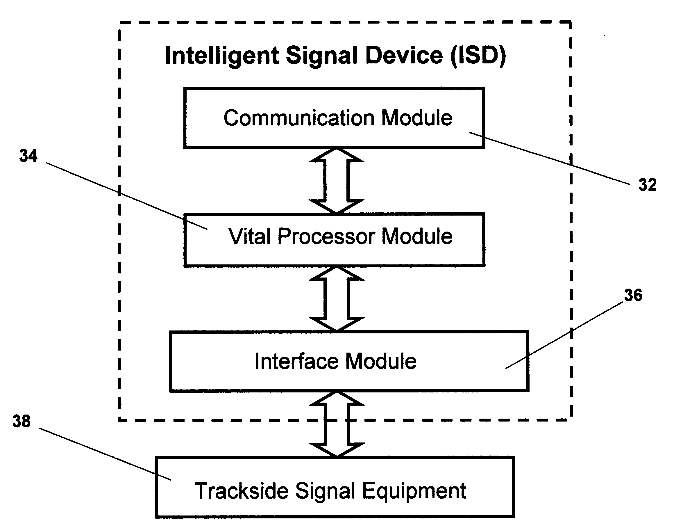
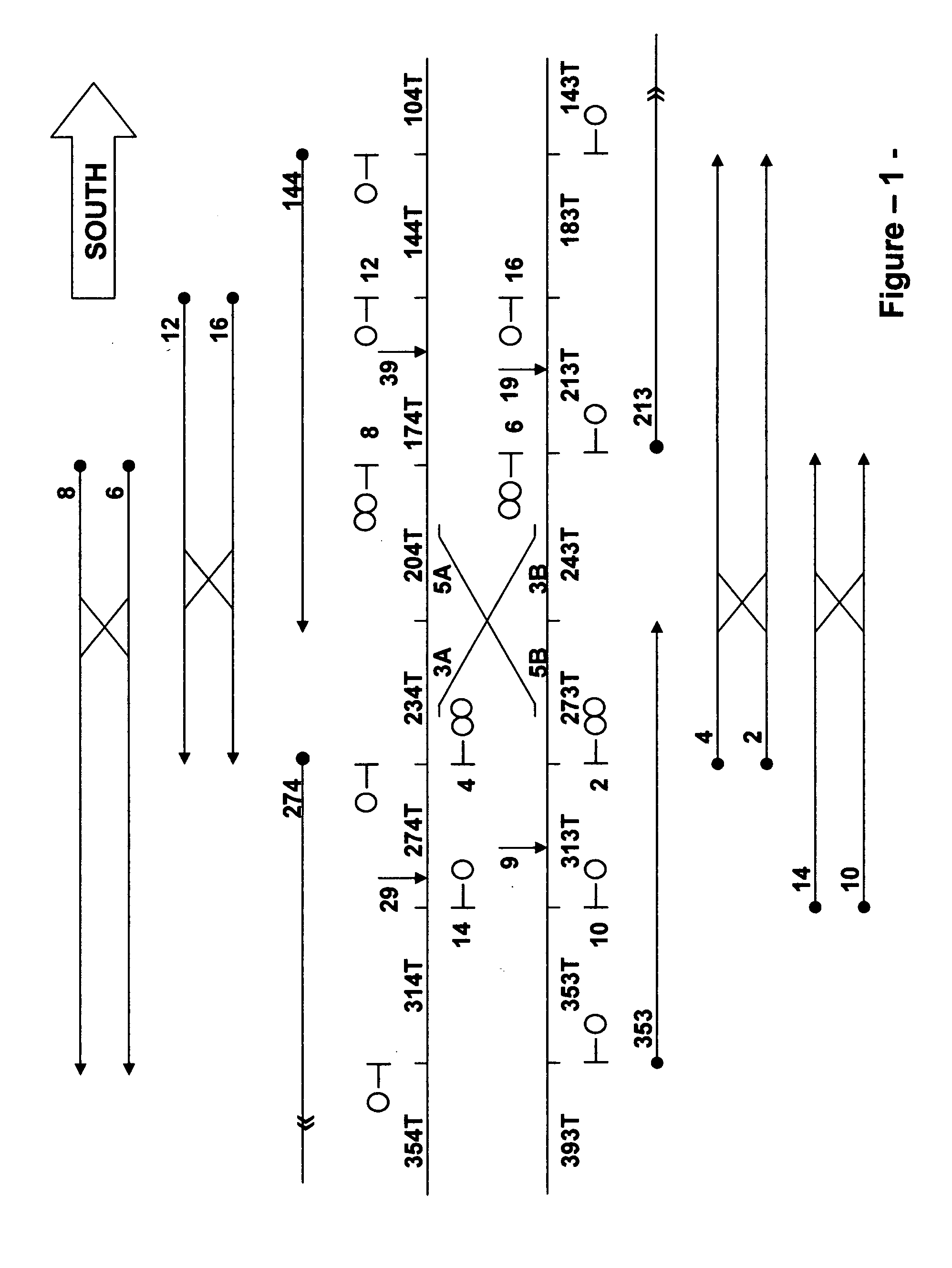
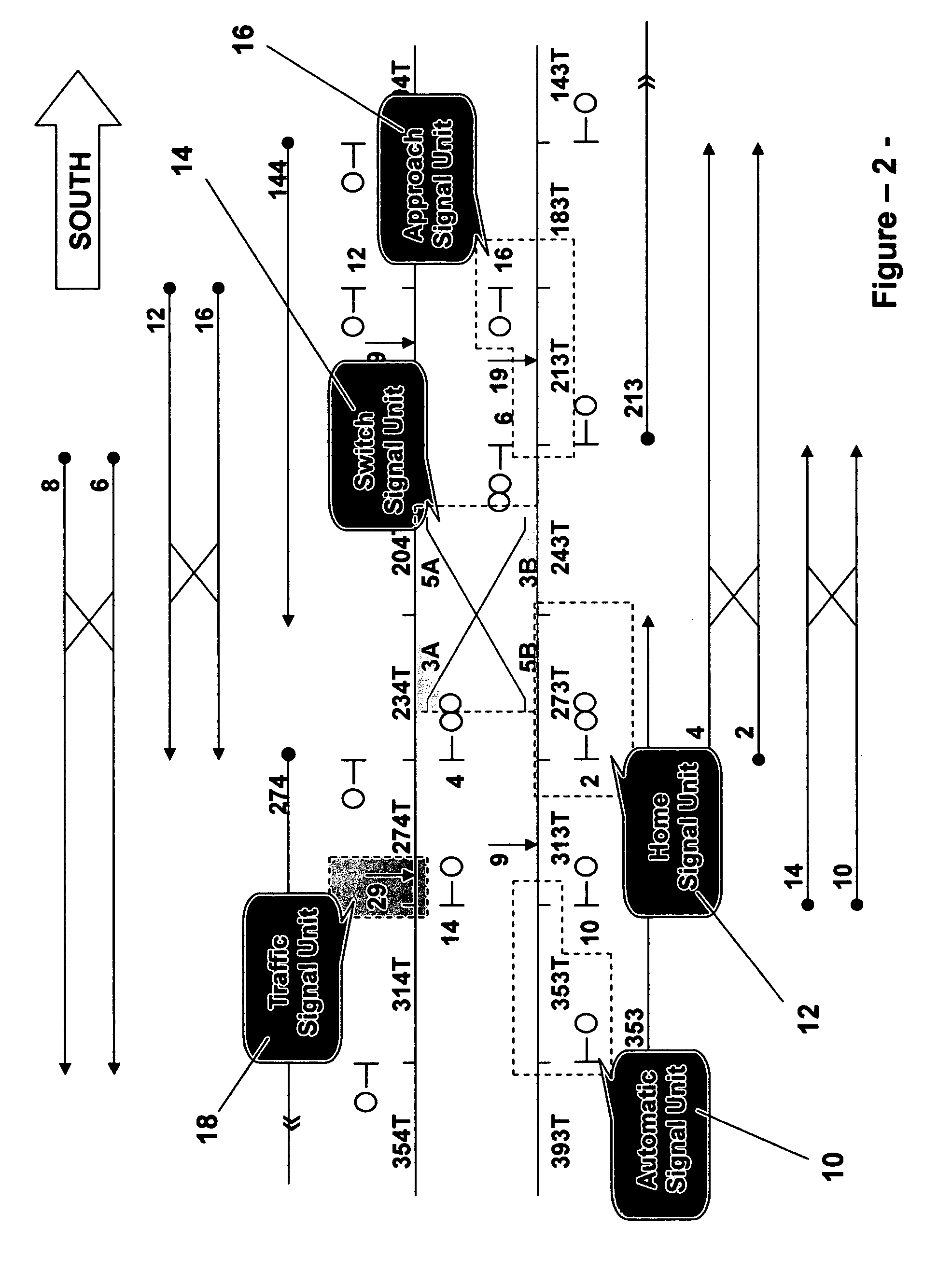
[0111]The preferred embodiment of the present invention provides a structure, or a process to control interlocking devices, and to control the safe operation of trains over sections of signaled track territory. For a typical interlocking installation that includes at least one track switch, a plurality of wayside signals and associated stop mechanisms (for transit application), and a plurality of detection blocks, the current invention configures the interlocking elements into a plurality of signal units, each of which has an independent vital control device. These vital control devices are interconnected by a data network that manages the data exchanges between the devices. Unlike a conventional interlocking that employs centralized control logic, the current invention segregates the interlocking control logic by type of interlocking element.

[0112]For example, in a typical interlocking configuration the control logic for track switch machines, home signals, approach signals, automa...


PUM


Abstract

A distributed interlocking device, architecture and process are disclosed, and are based on segregating the vital logic for a signal installation by type of signal equipment. A plurality of intelligent signal devices is disclosed, wherein each intelligent signal device is used to control a basic signal unit. In turn, a signal unit includes a set of signal apparatuses that are geographically and logically interrelated. An intelligent signal device receives data related to the states of other signal devices, determines and controls its own operational states, and communicates its own operational states to other devices.
A generic intelligent signal device is also disclosed, and is based on a parameterization approach that incorporates a plurality of vital parameters into the vital logic of the device. The device is then customized to a site specific location by activating the appropriate parameters for that location. In addition, a plurality of new concepts, and signal control functions are provided, and include a vital change management process, and a failure recovery scheme based on dynamic reconfiguration of home and distant control functions.

Description

[0001]This utility application benefits from provisional application of U.S. Ser. No. 61 / 004,824 filed on Nov. 30, 2007.BACKGROUND OF THE INVENTION[0002]1. Field of the Invention[0003]This invention relates generally to train control systems, and more specifically to a distributed solid state interlocking that includes a plurality of intelligent wayside signal devices such as track circuits, signal aspects, traffic controllers, track switch machines, automatic train stop machines, etc. An intelligent signal device makes its own determination related to the functionality and operation of the device, and continuously monitors its own state. For example, an intelligent signal determines its own aspect, and the position of its associated stop mechanism when used in transit applications. Similarly, an intelligent switch determines if the switch should be locked or not, and monitors the position and status of the switch. The intelligent wayside devices are interconnected together by a dat...

Claims


Application Information

Patent Timeline
Patent Type & Authority Applications(United States)
IPC IPC(8): G06F17/00
CPCB61L2019/065B61L19/06
Inventor GHALY, NABIL N.
Owner SIEMENS IND INC
Why Eureka
Try Eureka