
Composite coatings for whisker reduction

Active Publication Date: 2009-06-11
MACDERMID ENTHONE INC
View PDF53 Cites 25 Cited by
  • Summary
  • Abstract
  • Description
  • Claims
  • Application Information

AI Technical Summary

Benefits of technology

[0006]Among the various aspects of the present invention may be noted methods and compositions for depositing composite coatings comprising tin and non-metallic particles onto substrates such as electrical components. The deposited composite coatings are characterized by increased corrosion resistance, decreased friction coefficient, and increased resistance to tin whisker growth.

Problems solved by technology

The growth of tin whiskers is a well known but poorly understood problem with pure tin coatings.
Tin whiskers may grow between a few micrometers to a few millimeters in length, which is problematic because whiskers may electrically connect multiple features resulting in electrical shorts.
The problem is particularly pronounced in high pitch input / output components with closely configured features, such as lead frames and connectors.
Tin whiskers in the tin coating present a problem of shorts between electrical contacts.

Method used


Image

  • Composite coatings for whisker reduction
  • Composite coatings for whisker reduction
  • Composite coatings for whisker reduction

Examples


example 1

Electrolytic Plating Composition for Depositing a Composite Coating Comprising Tin and Fluoropolymer Particles

[0084]A composition for electrolytically plating a bright, glossy tin-based composite coating comprising fluoropolymer particles was prepared comprising the following components:[0085]100-145 g / L Sn(CH3SO3)2 (40 to 55 g / L Sn2+ ions)[0086]150-225 mL / L CH3SO3H (70% methane sulfonic acid solution in water)[0087]20 mL / L PTFE dispersion[0088]80-120 mL / L Stannostar® 1405 Additives

[0089]The pH of the composition was about 0. One liter of this composition was prepared. The PTFE dispersion used in this Example and in Example 2 is the 5070AN dispersion available from DuPont which comprises nanoparticles and a non-ionic surfactant. The Stannostar additives include a cationic surfactant. So in Examples 1 and 2 the particles are pre-wet with the non-ionic surfactant, but are not pre-wet with the cationic surfactant.

example 2

Electrolytic Plating Composition for Depositing a Composite Coating Comprising Tin and Fluoropolymer Particles

[0090]A composition for electrolytically plating a bright, glossy tin-based composite coating comprising fluoropolymer nanoparticles was prepared comprising the following components:[0091]100-145 g / L Sn(CH3SO3)2 (40 to 55 g / L Sn2+ ions)[0092]150-225 mL / L CH3SO3H (70% methane sulfonic acid solution in water)[0093]40 mL / L PTFE dispersion[0094]80-120 mL / L Stannostar® 1405 Additives

[0095]The pH of the composition was about 0. One liter of this composition was prepared.

example 4

Electrolytic Deposition of a Pure Tin Layer and a Composite Coating Comprising Tin and Fluoropolymer Particles

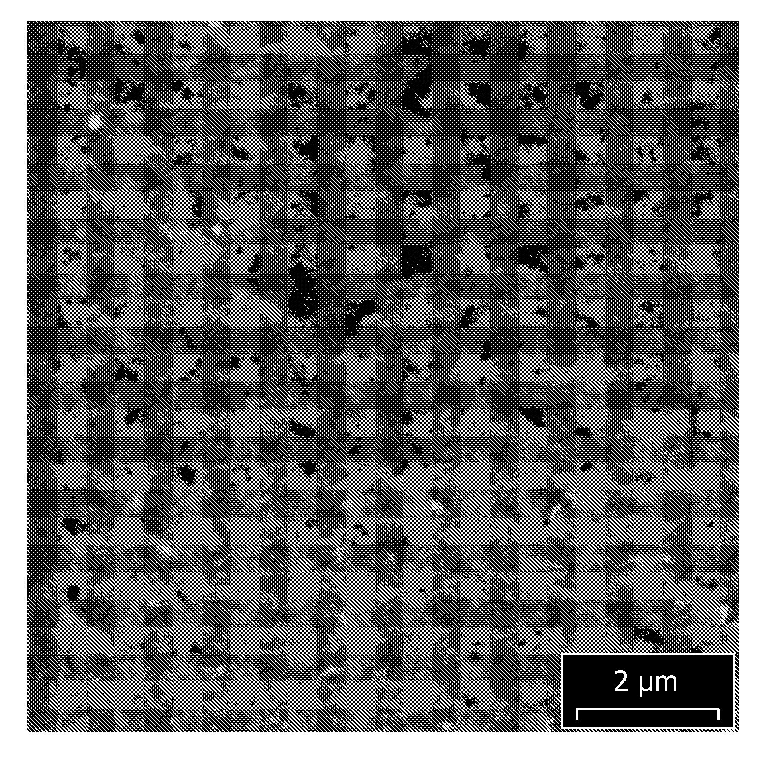
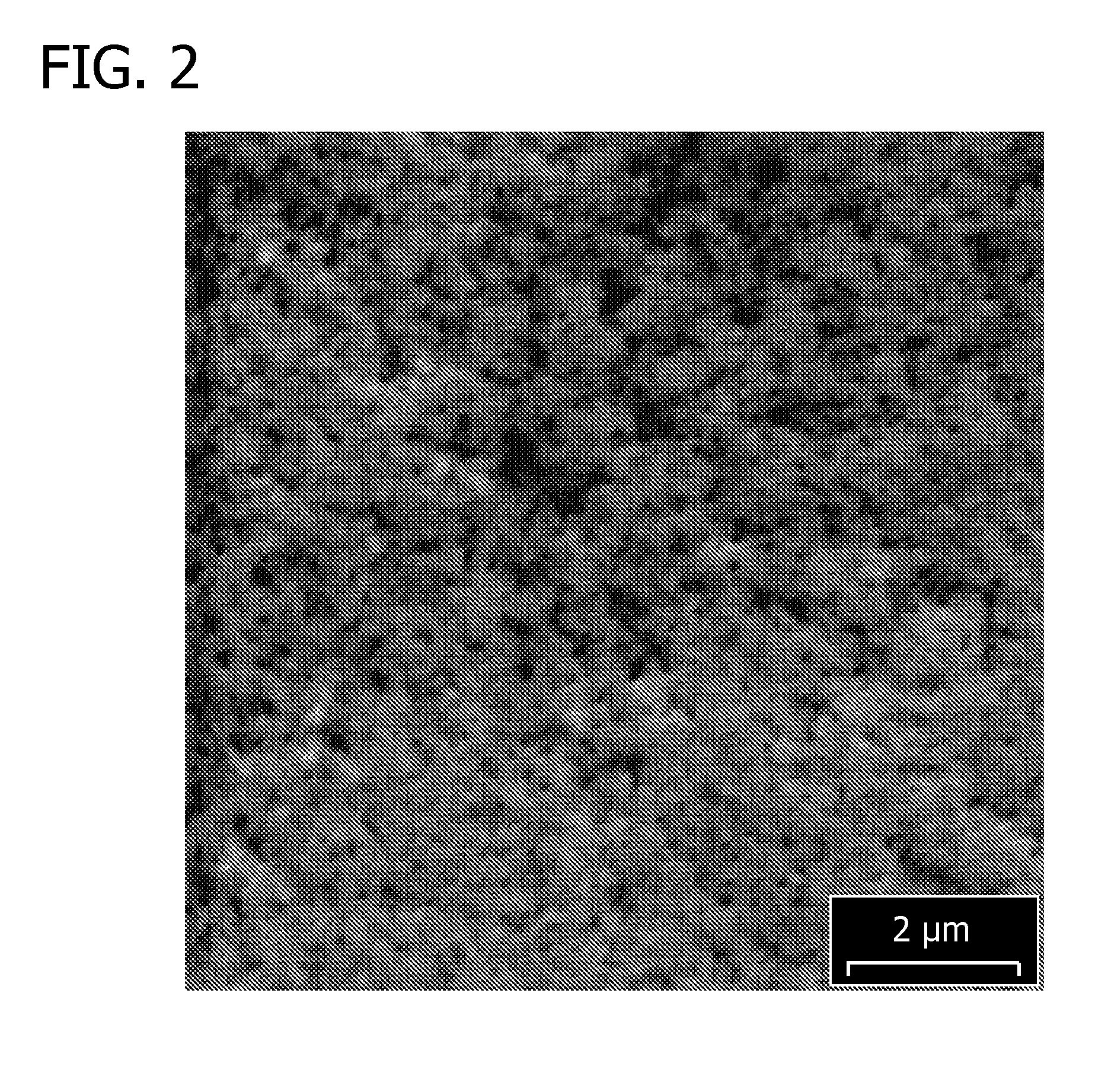
[0101]Two bright composite coatings comprising tin fluoropolymer nanoparticles (using the electrolytic plating compositions of Examples 1 and 2) and one bright, pure tin deposit (using the electrolytic plating composition of Example 3) were plated onto copper foils. The samples were plated in a beaker and the agitation was provided using a stir bar. To deposit the composite coatings comprising tin and fluoropolymer nanoparticles, the applied current density was 15 ASD, the plating duration was 50 seconds, and the deposit thickness was 5 micrometers, for a plating rate 6 micrometers per minute. SEM images of the freshly deposited composite coatings were obtained and are shown in FIG. 2 (composite coating obtained from composition of Example 1, scale=2 μm) and in FIG. 3 (composite coating obtained from composition of Example 2, scale=5 μm).

[0102]To deposit the pure tin coating...


PUM

PropertyMeasurementUnit
Densityaaaaaaaaaa
Densityaaaaaaaaaa
Percent by volumeaaaaaaaaaa

Abstract

There is provided a method and composition for applying a wear resistant composite coating onto a metal surface of an electrical component. The method comprises contacting the metal surface with an electrolytic plating composition comprising (a) a source of tin ions and (b) non-metallic particles, and applying an external source of electrons to the electrolytic plating composition to thereby electrolytically deposit the composite coating onto the metal surface, wherein the composite coating comprises tin metal and the non-metallic particles.

Description

REFERENCE TO RELATED APPLICATION[0001]This is a continuation-in-part of application Ser. No. 11 / 953,936 filed on Dec. 11, 2007, the entire disclosure of which is incorporated by reference.FIELD OF THE INVENTION[0002]This invention relates to methods of depositing composite coatings comprising tin and non-metallic particles, the composite coatings being characterized by increased wear resistance, corrosion resistance, and enhanced resistance to tin whisker formation.BACKGROUND OF THE INVENTION[0003]For much of its history, the electronics industry has relied on tin-lead solders to make connections in electronic components. Under environmental, competitive, and marketing pressures, the industry is moving to alternative solders that do not contain lead. Pure tin is a preferred alternative solder because of the simplicity of a single metal system, its favorable physical properties, and its proven history as a reliable component of popular solders previously and currently used in the ind...

Claims


Application Information

Patent Timeline
IPC IPC(8): C25D15/00
CPCC25D15/02C25D3/30H01R13/03
Inventor ABYS, JOSEPH A.LI, JINGYEKUDRAK, JR., EDWARD J.XU, CHEN
Owner MACDERMID ENTHONE INC
Learn More