Inner container surrounded by an outer container, used for receiving a cryogenic liquid

a cryogenic liquid and inner container technology, applied in the field of inner containers, can solve the problems of large volume of conventional reinforcement measures for tanks with large planar surfaces, poor space utilization, and insufficient strength and stability

Inactive Publication Date: 2009-06-11
MAGNA STEYR FAHRZEUGTECHN
View PDF9 Cites 14 Cited by
  • Summary
  • Abstract
  • Description
  • Claims
  • Application Information

AI Technical Summary

Problems solved by technology

However, only poor space utilization is possible in this way; steel tanks of said type take up the entire luggage space of a motor vehicle.
This creates the problem of obtaining sufficient strength and stability, in particular sufficient stiffness or rigidity against buckling, of the tank.
Conventional reinforcement measures for tanks with large planar surfaces are usually very massive.
Thick sheet-metal wall thicknesses entail both complex production techniques and also joining techniques as a result of a large number of web plates or bulkhead plates used in the cryogenic inner tank; a high weight is the ultimate result.
Although expedient space utilization is possible in this way, especially since the tank may be adapted to the available stowage space, it is however disadvantageous that a separate tank must be developed for each motor vehicle model, which in any case also always entails new dies and tools.

Method used


Image

  • Inner container surrounded by an outer container, used for receiving a cryogenic liquid
  • Inner container surrounded by an outer container, used for receiving a cryogenic liquid
  • Inner container surrounded by an outer container, used for receiving a cryogenic liquid

Examples


Embodiment Construction

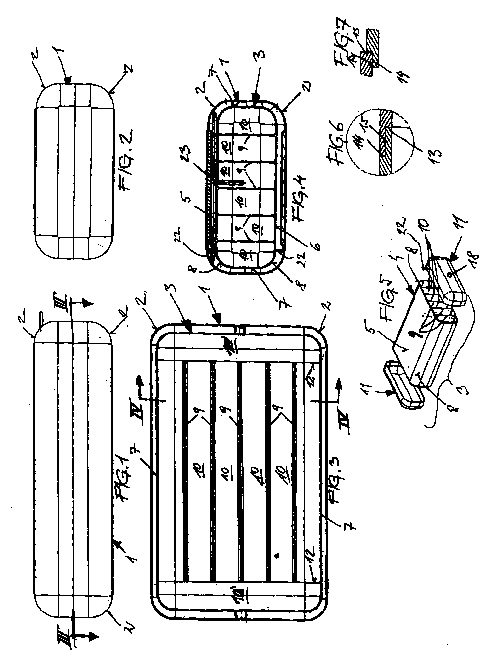
[0057]The invention is explained in more detail below on the basis of a plurality of non-restrictive exemplary embodiments which are illustrated in schematic drawings, wherein:

[0058]FIG. 1 showing a side view;

[0059]FIG. 2 an end view of an outer tank in which, to hold a cryogenic fuel, an inner tank is arranged;

[0060]FIG. 3 shows a section through the outer tank as per the line III-III in FIG. 1;

[0061]FIG. 4 shows a section as per the line IV-IV of FIG. 3;

[0062]FIG. 5 shows an exploded illustration of the inner tank before its assembly;

[0063]FIG. 6 and FIG. 7 show different designs of a weld seam for the inner tank;

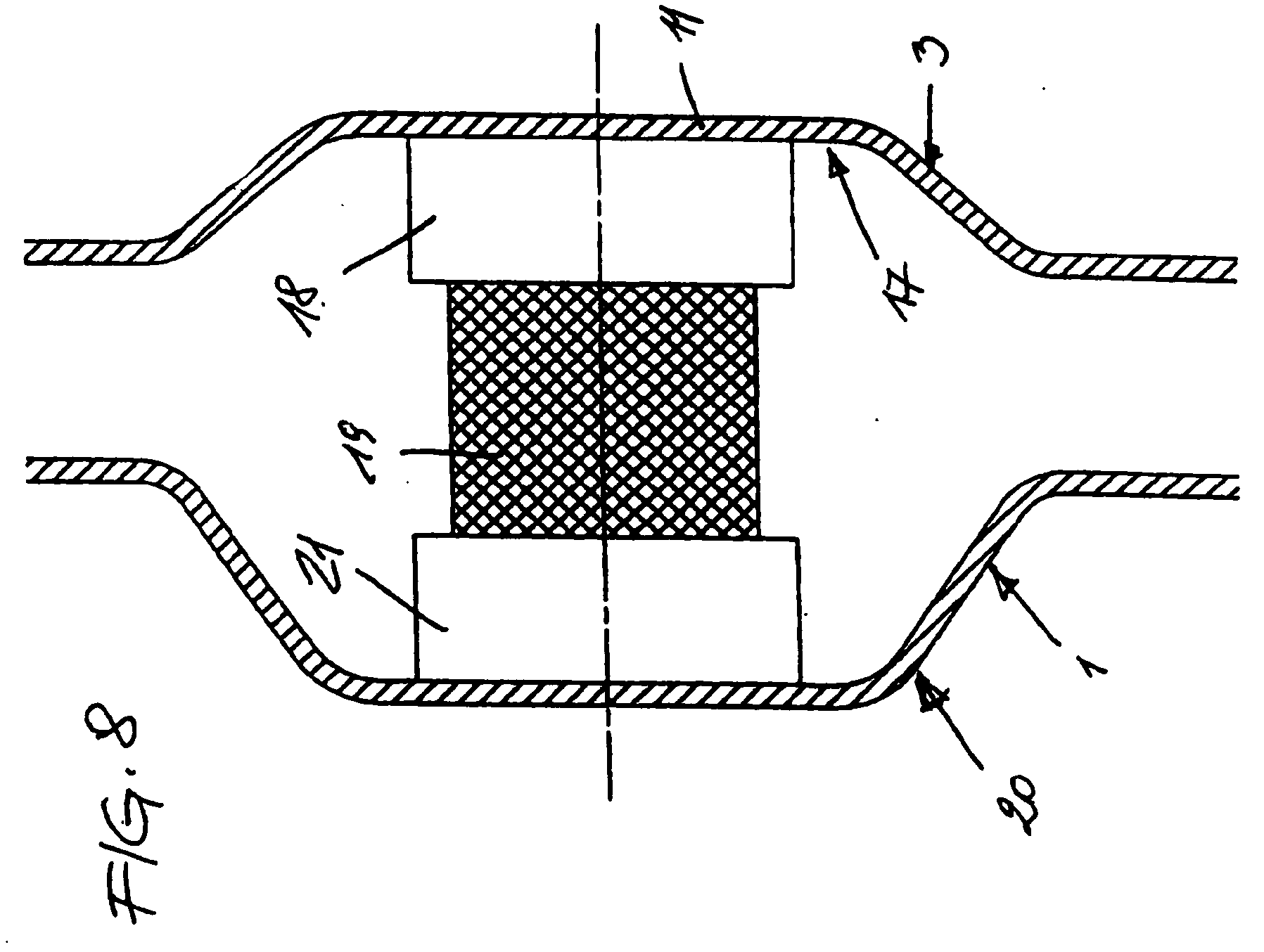
[0064]FIG. 8 details an arrangement for suspending the inner tank on the outer tank;

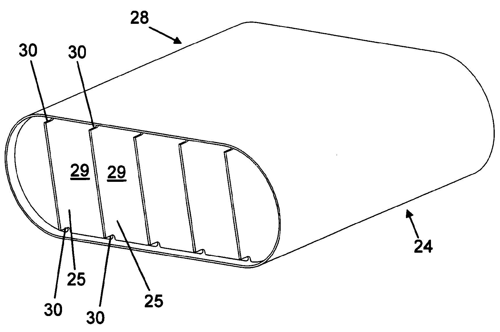
[0065]FIG. 9 shows a side view in the longitudinal direction of the inner tank which is open at the side;

[0066]FIG. 10 shows an axonometric view of the basic body;

[0067]FIG. 11 shows a section through and along one of the webs and the cap of the inner tank;

[0068]FIG. 12 shows an axonometri...


PUM


Abstract

A flat inner container (3), especially an internal tank for a road vehicle, which is surrounded by an outer container (1) and is used for receiving a cryogenic liquid, particularly a fuel. The inner container (3) comprises a combination of the following features: a longitudinally extending monolithic base (4) with a top wall (5) and a bottom wall (6) which are connected to also longitudinally extending sidewalls (7), and with at least two longitudinally extending, substantially straight webs (9) that connect the bottom wall (6) to the top wall (5) so as to form at least one longitudinally extending chamber (10) which is arranged between the webs, extends along the entire length of the base (4) as well as from the bottom wall (6) to the top wall (5), and has a predetermined width between the webs; and at least two caps (11) which tightly seal the two open ends of the base (4) at the periphery; the top wall and/or the bottom wall is/are provided with an arch relative to a planar reference top wall and/or reference bottom wall, the distance of the arch between the inner contour of the top wall and/or the bottom wall and the planar reference top wall and/or reference bottom wall amounting to less than 30 percent of the width of the chamber in the center between the webs.

Description

BACKGROUND OF THE INVENTION[0001]The invention relates to an inner tank, of flat design, which is surrounded by an outer tank and serves to hold a cryogenic liquid, in particular a fuel, in particular an inner tank for a road-going vehicle.[0002]Usually, for use in motor vehicles, cryogenic fuels are inserted into cylindrical, that is to say barrel-shaped tanks which are designed as double-walled steel tanks. However, only poor space utilization is possible in this way; steel tanks of said type take up the entire luggage space of a motor vehicle. DE 101 63 029 A1 presents a barrel-shaped high-pressure hydrogen tank of said type in which an inner polyethylene lining is surrounded by an outer winding which is intended to prevent a bulging effect.[0003]A flat, cuboidal design of tanks for cryogenic fuels is desirable in particular for use in motor vehicles. This creates the problem of obtaining sufficient strength and stability, in particular sufficient stiffness or rigidity against bu...

Claims


Application Information

Patent Timeline
Patent Type & Authority Applications(United States)
IPC IPC(8): B60K15/03F17C1/02F17C1/14
CPCF17C3/00F17C2270/0168F17C2201/0157F17C2201/0166F17C2201/0171F17C2201/035F17C2201/056F17C2203/013F17C2203/014F17C2203/015F17C2203/03F17C2203/0629F17C2203/0646F17C2203/0648F17C2209/2109F17C2209/221F17C2209/222F17C2209/227F17C2209/228F17C2209/232F17C2209/234F17C2221/01F17C2223/0161F17C2223/033F17C2250/0408F17C2250/043F17C2250/0439F17C2260/012F17C2201/0147
Inventor HAUSBERGER, KLAUS
Owner MAGNA STEYR FAHRZEUGTECHN
Why Eureka
Try Eureka